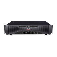
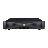
1XP 600/1000/2000/2100/3000/3100/5000/5100
English
INTRODUCTION
Thank you for choosing XP series power amplier. The unit is
designed to provide a good combination of power, audio clarity,
reliability and durability. An efcient heat-dissipation system
comprising a high-surface area heat sink coupled with two
variable speed fans ensures quiet and reliable cooling. Good
sound quality and sturdy construction make this unit ideal for
a multitude of amplication tasks; from studio installations to
mobile DJs, house of worship and touring bands. In order to
get the best performance out of your XP series power ampli-
er, please read this user’ s manual carefully, and retain it for
future reference.
FEATURES
● Advanced powerful performance- third generation
circuitry design
● High continuous current output from robust toroidel
transformer
● Switchable input peak limiter and selectable high pass lter
(30 Hz, 50 Hz) to reduce distortion and protect speakers
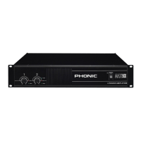
● Two front mounted detented gain controls
● User selectable low pass lters (XP2100, XP3100
and XP5100 only)
● Selectable stereo, parallel & bridge mono amp modes
● Ground Lift-switch to help against humming
● Signal level at -40, -20, -10, protect and clip LED
indicators to monitor performance
● Bridge mono and parallel mode LEDs
● Fast Recovery design for lower distortion if clipping occurs
● Active balanced inputs for low noise
● XLR/TRS connectors for maximum input exibility
● Barrier strip input connectors on the XP5000 and XP5100
for permanent installations
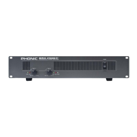
● Speakon and 5-way binding post speaker outputs
● 2 ventilation variable speed fans
● Very rugged housing
● Fits a standard 19” rack
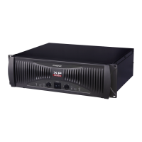
INSTALLATION
MOUNTING
The power amplifier can be installed in a standard 19-
inch equipment rack. It requires 3 units (5.25 inches)
for the XP 2000/2100, XP 3000/3100, and 2 units (3.5
inches) for the XP600/1000 of vertical rack space and
secures to the rack cabinet with four rack mount
screws and cup washers. In a rack, it is best to mount
units one above the other, with at least a unit of space at least
between two ampliers. This provides efcient airow and support.
COOLING
Two variable-speed fans would start running as soon as the power
is being turned on. Before mounting your amplier, you should
familiarize yourself with its cooling requirements. The air ows from
the front to the back, so it is important not to block the amplier
front air vents. If the amplier is rack-mounted, leave some space
in front of the rack to prevent heated air being drawn back into
the front-to-back airow. Airow restrictions are the most com-
mon cause of inadequate cooling. They may result from improper
mounting, bundles of power cords, clogged dust lters and closed
rack doors. Mount the amplier to allow sufcient airow out the
front outlets to ensure your amplier work properly.
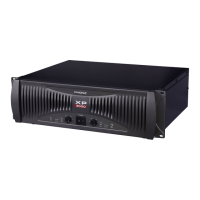
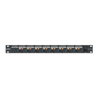
WIRING
The balanced XLR and TRS input connectors will accept the
line-level output of most devices for ultimate input convenience.
The amplier built-in XLR and TRS connectors can be wired simi-
larly for balanced or unbalanced, oating or ground-referenced
sources. The output connector is a binding post with Speakon
which provides an easy connection when using banana plugs,
spade lugs or bare wires.