3XP 600/1000/2000/2100/3000/3100/5000/5100
English
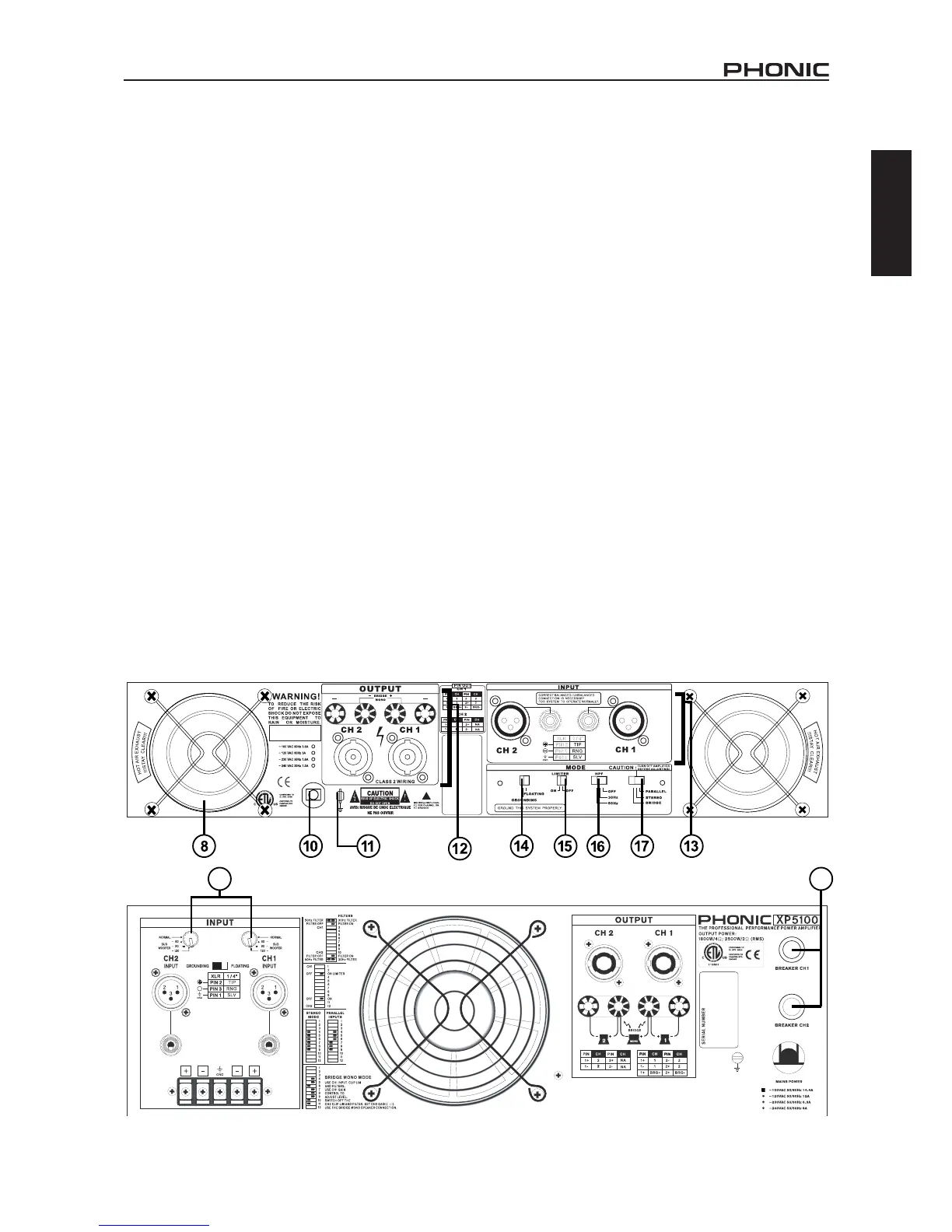
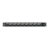
REAR PANEL DESCRIPTION
7. SUBWOOFER SWITCH (XP2100/3100/5100 ONLY)
NORMAL/60/90/120Hz
Switching from normal to either 60Hz, 90Hz or 120Hz setting will
add the dedicated low pass lter to the output path, which offers
you a sub bass output to achieve a 3-way or more ways speaker
system. When you activate this function, you will get the subwoofer
frequency output below 60Hz, 90Hz or 120Hz only. On the XP5100
this switch is located on the rear of the amplier.
8. FAN
These two variable speed fans automatically maintain safe in-
ternal temperature. Keep the front and rear vents clear to allow
full airow. Hot air will be drawn out the back of the amplier, so
it does not stay in the rack, and make sure plenty of cool air can
enter the rack.
9. RESET BREAKER
With rated loads and output levels, the breaker should only shut
down the amplier in rare instances of catastrophic failure. The
circuit breaker can also shut down the amplier in cases where
extremely low-impedance loads and high output levels result in
a current draw that exceeds its rating.This feature is not included
on the XP600.
10. POWER CORD
All units are shipped with an appropriate plug and cord for the
required AC voltage. This product is equipped with a 3-wire
grounding type plug. This is a safety feature and should not be
defeated. Check the AC voltage before connecting the plug.
11. CHASSIS GROUNDING CONNECTING POINT
Please refer to your local safety code for proper grounding.
12. OUTPUT CONNECTORS
A pair of versatile binding posts and Speakon connectors are
provided for output connection to each channel. Loudspeak-
ers can be easily connected using banana plugs, spade lugs,
bare wires or Speakon connector. Spade lugs and bare wires
should both be screwed down tightly to avoid a short circuit. The
Speakon connector for channel 1 includes channel 1, channel 2
and bridged mono pin connecting points. A pin out information
could be foundbeside the Speakon connector.
13. INPUT CONNECTORS
The power amplier offers XLR and TRS input connectors for your
connecting convenience. On the XP5000 and 5100, users will also
nd barrier strip inputs. Barrier strip inputs should be screwed
down tight as to not let oxygen enter the connection. These are
best used in long term or permanent installations.
14. GROUNDING - FLOATING SWITCH
This switch allows the circuit and chassis grounding to be sepa-
rated in case of a grounding conict. In normal use, the switch
should be in the grounding on position. Lifting the grounding
(to what is called the oating position) may resolve the ground
conict, but it means that circuit grounding depends on other con-
nected equipment. Deciencies in other components’ grounding
will affect the sound quality and cause a grounding loop hum.
For the best combination of safety and performance, it is highly
recommended to set the switch at the “grounding on” position.