2 XP 600/1000/2000/2100/3000/3100/5000/5100
English
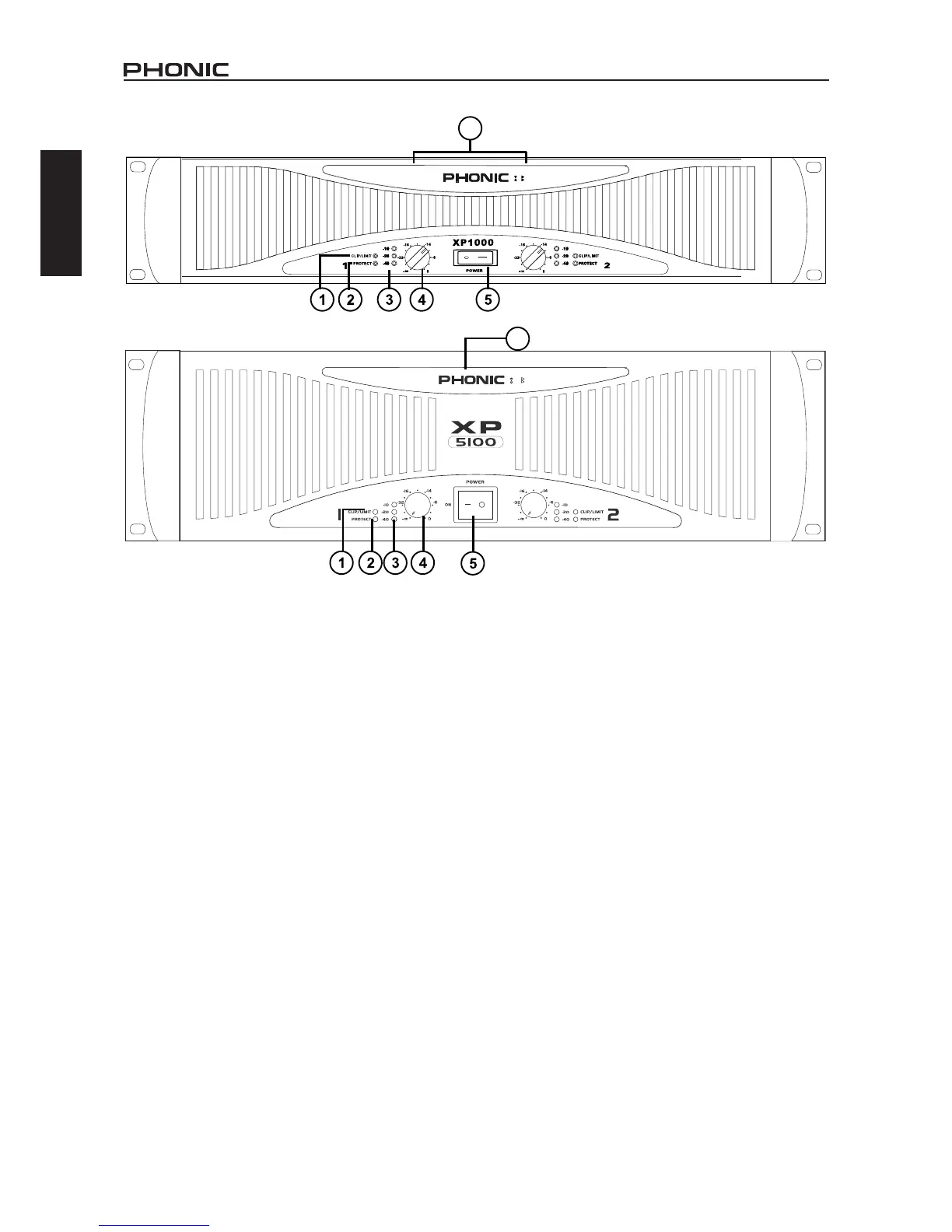
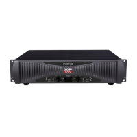
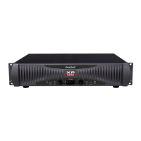
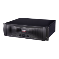
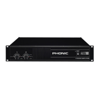
FRONT PANEL DESCRIPTION
1. CLIP/LIM LED (RED)
When the audio signal drives the amplier output circuit beyond
its power capability, it will clip. The peak limiter detects this and
quickly reduces the gain to minimize the amount of overdrive, so
as to preserve as much of the program dynamics as possible.
2. PROTECT LED (YELLOW)
The power amplier features several types of protection to pre-
vent damage to the circuitry during turn-on or fault conditions.
The power-on protection relay prevents damaging thumps to the
speakers as the power comes on. When the amplier is switched
on, the protect LED will light for a few seconds, and then go out,
indicating that the relay has closed, connecting the speakers to
the amplier.
The protect LED will also come on if the speaker terminals are
short circuited, or the impedance of the load between them is
too low. Under these circumstances, the protect LED will stay on
until the fault condition is rectied.
If the amplier’ s large heat sinks go down for thermal reasons,
leave the power connected to the amplier, try to improve ventila-
tion, and reduce the gain. Without power, the fan cannot oper-
ate, and the amplier will require longer to reach a low enough
temperature to restart.
3. SIGNAL LED (GREEN)
Each channel of the power amplier features a signal light to show
that how much of an audio signal has been put in to the channel.
The threshold for the indicator is -40dB, above that, noise will
trigger the LED to light.
4. GAIN CONTROL
These two knobs are the level controls for each channel of the
amplier. The gain increases as the knob is turned clockwise.
This unit features detented gain controls.
5. POWER SWITCH
Although the XP series ampliers feature power-on muting, it is
always a good practice to reduce both the gain controls before
turning on the amplier. The powering-up procedure for an audio
system should start from instruments and then mixer, and you
should verify that all system operations are normal before turn-
ing on the amplier.
6. DISPLAY
When the amplier is switched to the bridge mono mode, the
bridge LED right next to the PHONIC logo will light up in red.
When the amplier is switched to the parallel mode, the parallel
LED next to the bridge LED will light up in yellow.