5: High beams and tail lights on - Contacts 30/2 -
56 a/2 - 30/3 - 56 a/1.
APE TM P703 FL2 (VERSION WITH STEERING
WHEEL)
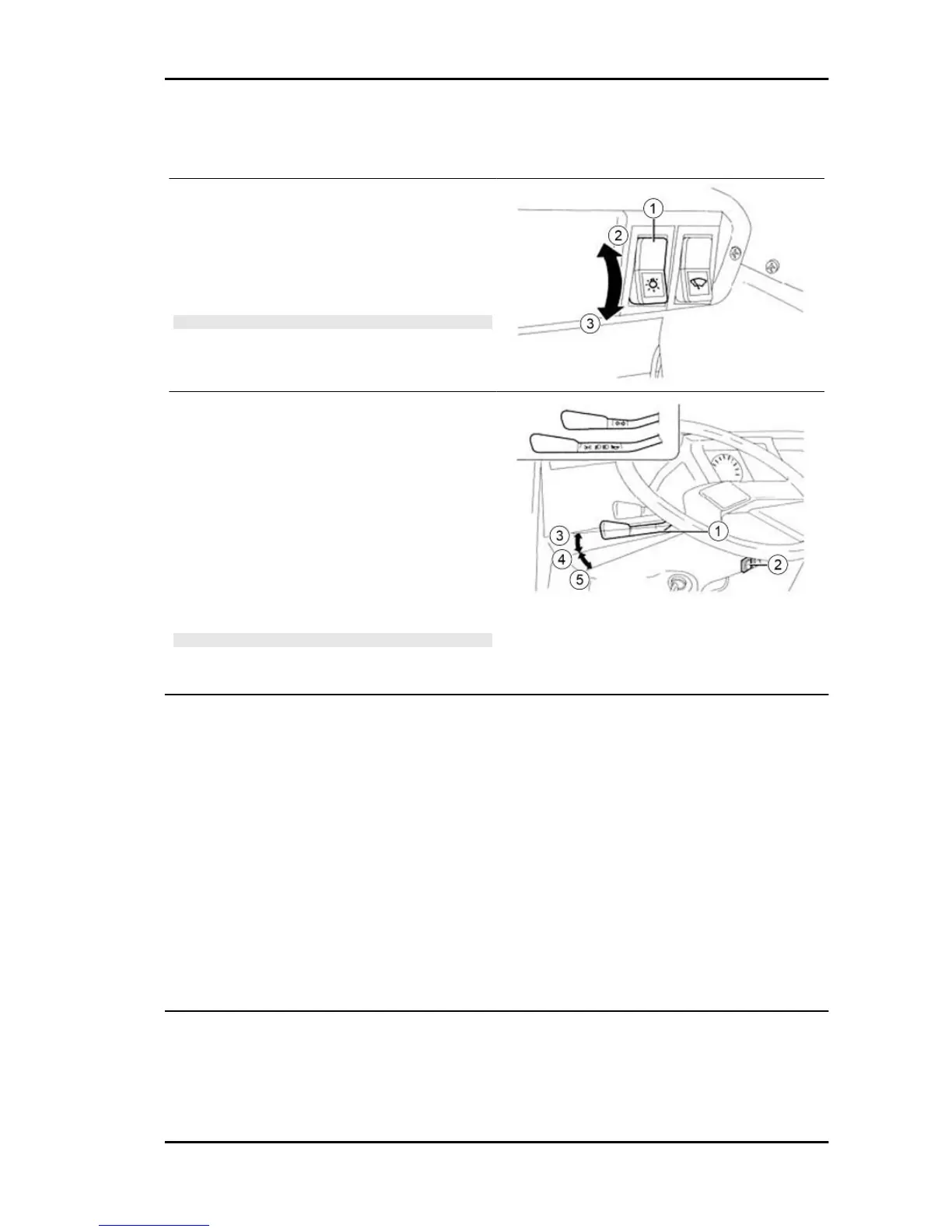
Positions of the external lights switch "1":
2 = Lights off.
3 = Lights on.
N.B.
WHEN THE SWITCH IS SET TO POSITION "3", THERE
MUST BE CONTINUITY BETWEEN THE WHITE-RED AND
RED-GREY CABLES.
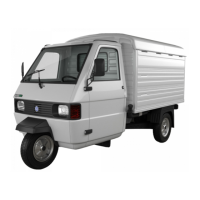
APE TM P703 FL2 (VERSION WITH STEERING
WHEEL)
Positions of the light switch and horn lever "1" with
the external light switch "2" set to the ON position:
3 = Tail lights on - no contact.
4 = Low-beam lights and daylight running lights on
- contacts C - 56b.
5 = High-beam lights and daylight running lights on
- contacts 30/2 - 56a/2.
N.B.
THE SWITCH POSITIONS ARE SUBJECT TO THE POSI-
TION OF THE EXTERNAL LIGHTS CONTROL SWITCH.
Voltage regulator
The controller is basically composed of two groups:
a) Minimal switch, consisting of a nucleus, on which are mounted two coils (voltmeters, and ammeter).
b) Three-contact voltage regulator ("soft" voltage) also consists of a nucleus on which other two coils
are mounted, ammeter and voltmeters.
The minimal switch has the task of inserting the dynamo in the battery circuit when the dynamo reaches
a certain speed (coupling rpm) and switch it off as soon as a reverse current occurs, as well as verifying,
when the vehicle is stationary, that the tension of battery exceeds that of the dynamo.
The voltage regulator has the task of maintaining the voltage within limits that ensure a rapid charging
of the battery when it is low, and to prevent overloading, regardless of the speed variations and the
electrical charges activated.
Starter motor
OPERATION OF DYNAMOTOR
The dynamotor acts as a generator and as a starter motor. The creation of this device is a direct con-
sequence of the principle of reversibility of the dynamo and in particular of the dynamo excited in parallel,
APE TM Benzina Electrical system
ES - 61