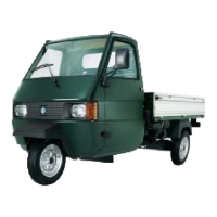
BALL BEARING
Fit the specific tool fitted with comp. 17, act on the
central screw (1) and remove the bearing and the
washer.
Specific tooling
T.0014499 Bearing extractor
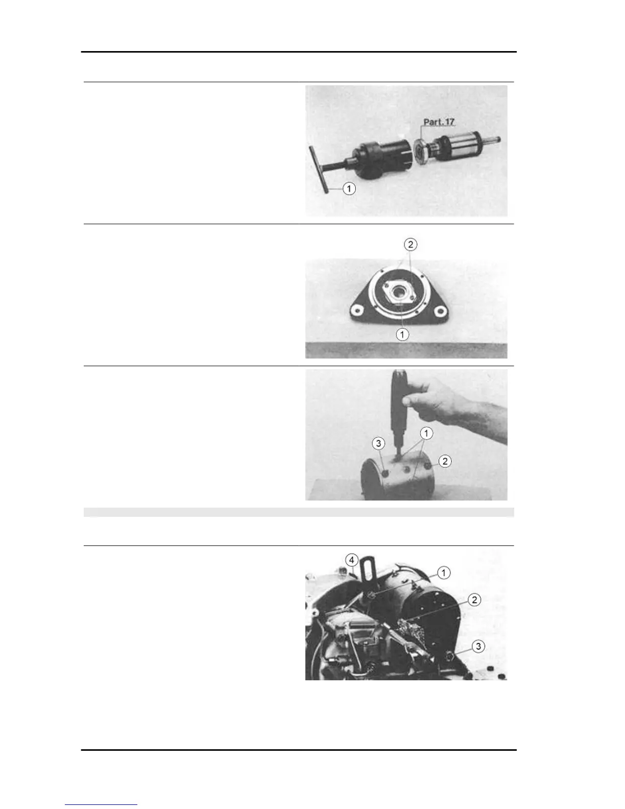
PULLEY SIDE BALL BEARINGS
Remove the flange using the four screws, unscrew
the two screws (2), remove the plate (1) and from
the part opposite to that shown in the figure, with
a punch of external Ø 22 mm eject the bearing.
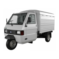
FIELD WINDINGS
With the help of a strike screwdriver, as shown in
the figure, remove the four anchor screws (1) of
the windings, unscrew the two nuts (3) and (2) and
remove the windings themselves.
N.B.
THE UNIT IS ASSEMBLED PROCEEDING IN THE OPPOSITE ORDER AS FOR REMOVAL AS DE-
SCRIBED ABOVE.
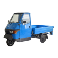
DYNAMOTOR - FITTING
The Dynamotor is assembled on the engine unit
as described above: position the dynamotor, an-
choring it to the crankcase with the relative bolts
without locking them, adjust the belt by moving the
dynamotor toward the rear of the engine and lock
the bolt (1), then the other two in the order shown
in the figure.
Remove the cap from the track (4) on the scroll
putting a pencil in contact with the belt, push the
pencil to the bottom and check its course; the belt
Electrical system APE TM Benzina
ES - 64