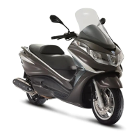
Check the signal
Move the positive rod to the position shown in the
photo. Turn the front wheel very slowly and check
that the measured voltage is 0 V or battery voltage,
depending on the position taken up.
This condition should be repeated 16 times during
a complete revolution of the wheel.
N.B.
THE DIGITAL MULTIMETER IS NOT ABLE TO DISPLAY
THE VOLTAGE WHEN THE WHEEL IS ROTATED FAST.
If other voltages are measured or there is no alternation, replace the tone wheel.
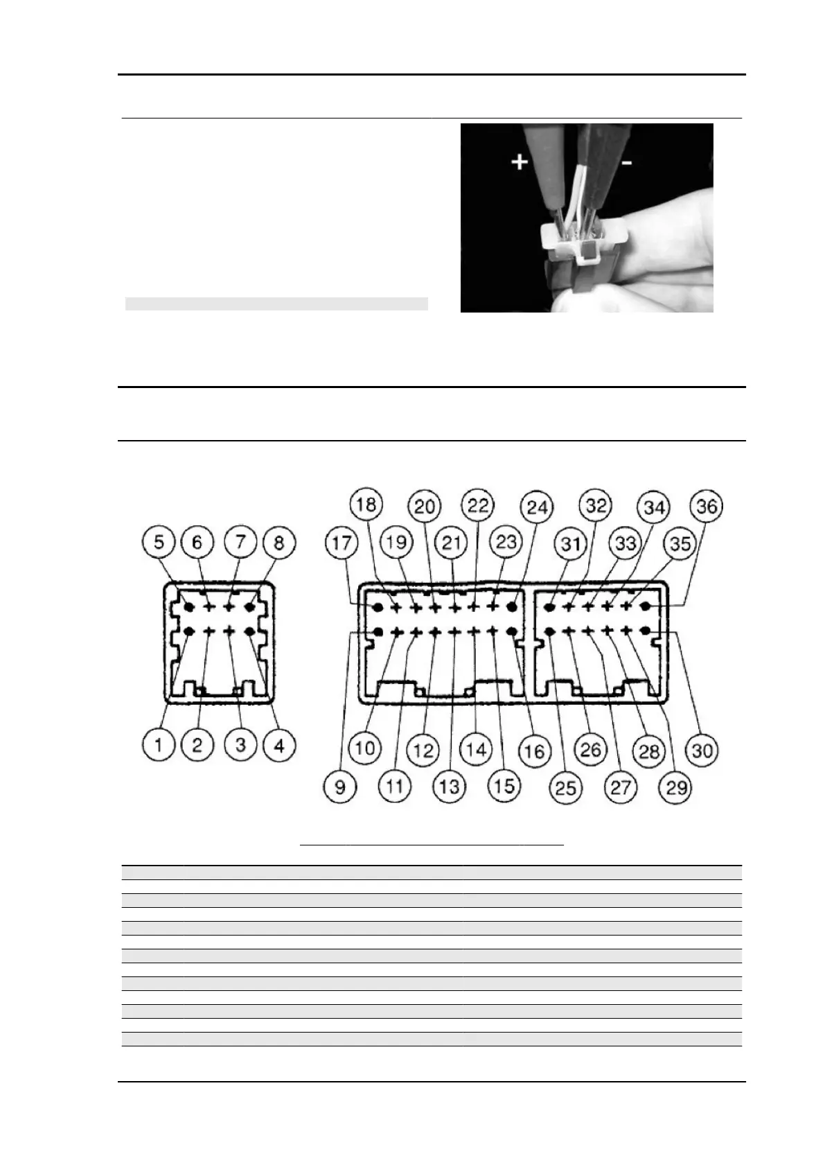
Connectors
ECU
DIGITAL DASHBOARD CONNECTOR AND WIRING
Specification
Desc./Quantity
1 Analogue card negative
2 Battery positive (+30) for analogue card
3 Analogue card serial clock output
4 Antitheft led output
5 Analogue card serial data output
6 Lights on output
7 (Not connected)
8 (Not connected)
9 Warning light input
10 Stuck relay alarm light input
11 Abs indicator input (not connected)
12 RH direction indicator output
13 RH direction indicator button input
14 LH direction indicator button input
X9 Evolution 500 Electrical system
ELE SYS - 79