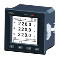
8.5. Description of SPM33 Registers
All SPM33 measured and setup parameters are treated as HOLDING
REGISTERS having addresses 4xxxx when communicating in MODBUS
protocol. According to the MODBUS Protocol, in response to a request for
register 4xxxx of a particular slave device (SPM33), the MODBUS master
reads register xxxx-1 from the slave (SPM33). For example register 40011
corresponds to register 10.
8.6 Description of Data Types
UINT16 Unsigned 16-digit integer
INT16 Signed 16-digit integer
LUINT32 Unsigned 32-digit integer
LINT32 Signed 32-digit integer
WORD16
Bit denotation word, applicable to on-off and relay status.
D0 refers to the first on-off or relay channel.
D1 refers to the second on-off or relay channel.
The rest bits may be deduced by analogy.
Bit 0 refers to “off”, and bit 1 refers to “on”.
42