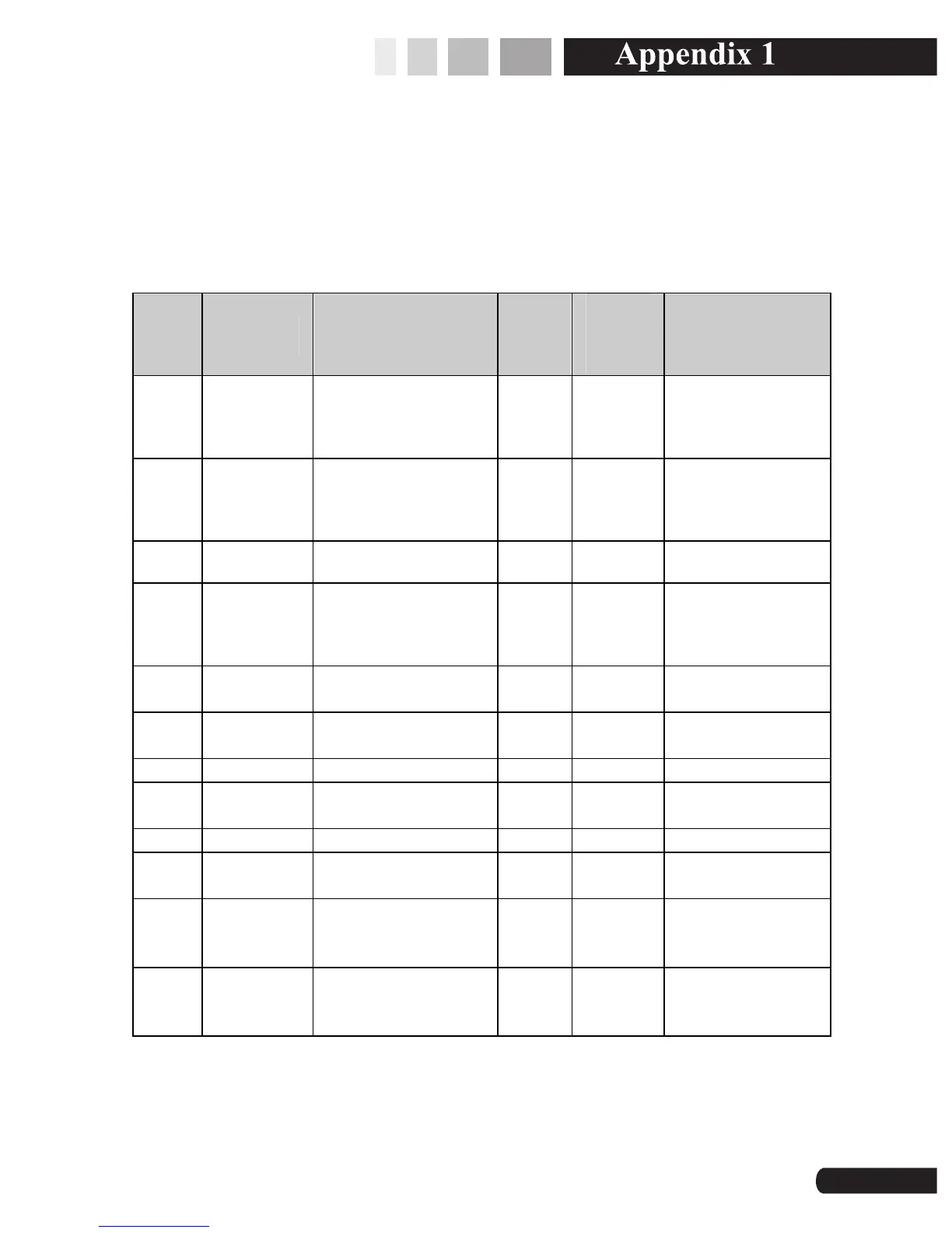
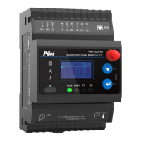
10. Appendix 1
10.1 Terminals Definition
No. Definition Instruction No.
Definiti
on
Instruction
1 L/+
Positive pole of
power supply
2 NC Null
3 N/-
Negative pole of
power supply
4 NC Null
5 S1 Status input 1 6 S2 Status input 2
7 SG
Status input
public GND
8 RL1
Relay 1 output
1
9 RLN1 Relay 1 Output 2 10 RL2
Relay 2 Output
1
11 RLN2 Relay 2 Output 2 12
RS485
-
485 positive
pole
13 RS485+ 485 positive pole 14 SHLD RS485 shield
15 VA phase A voltage 16 VB
phase B
voltage
17 VC phase C voltage 18 VN Neutral line
19 I11
Phase A current
incoming line
20 I12
Phase A current
outgoing line
21 I21
Phase B current
incoming line
22 I22
Phase B
current
outgoing line
23 I31
Phase C current
incoming line
24 I32
Phase C
current
outgoing line
69