- 2 -
• AC-Schaltgeräte haben einen
kurzschlussfesten Netztransformator.
DC-Schaltgeräte besitzen eine elektroni-
sche Sicherung.
Funktionsbeschreibung
Das Schaltgerät PNOZ 1 dient dem
sicherheitsgerichteten Unterbrechen eines
Sicherheitsstromkreises. Nach Anlegen der
Versorgungsspannung, Brücke zwischen
X1-X2 und T33-T34 sowie geöffnetem
Eingangskreis geht Relais K3 in Wirk-
stellung.
• Eingangskreis geschlossen (z. B. NOT-
AUS-Taster nicht betätigt) Relais K1 und
K2 gehen über die Schließer K3.1 und
K3.2 in Wirkstellung und halten sich selbst
über K1.1 bzw. K2.1. Die Statusanzeigen
leuchten. Die Sicherheitskontakte (13-14/
23-24/33-34) sind geschlossen, der
Hilfskontakt (41-42) ist geöffnet.
• Eingangskreis wird geöffnet (z. B. NOT-
AUS-Taster betätigt) K1 und K2 fallen in
die Ruhestellung zurück. Die Sicherheits-
kontakte (13-14/23-24/33-34) werden
redundant geöffnet, der Hilfskontakt
(41-42) geschlossen.
Function Description
The relay PNOZ 1 provides a safety-
oriented interruption of a safety circuit.
When the operating voltage is supplied,
X1 - X2 and T33 - T34 are bridged and the
input circuit is closed, relay K3 energises.
• Input circuit closed (e.g. Emergency Stop
Button not activated): Relays K1 and K2
energise via the N/O K3.1 and K3.2 and
latch via K1.1/K2.1. The status indicators
illuminate. The safety contacts (13-14/23-
24/33-34) are closed, the signal contact
(41-42) is opened.
• Input circuit opened (e.g. Emergency Stop
Button activated): K1 and K2 de-energise.
The safety contacts (13-14/23-24/33-34)
are opened redundantly, the signal contact
(41-42) is closed.
• transfo. interne protégé contre les c.c
(relais en AC)
• fusible électronique (relais en DC)
Betriebsarten:
• Einkanaliger Betrieb:
Eingangsbeschaltung nach VDE 0113
und EN 60204, keine Redundanz im
Eingangskreis; Erdschlüsse im Taster-
kreis werden erkannt.
• Zweikanaliger Betrieb: Redundanter Ein-
gangskreis; Erdschlüsse im Tasterkreis
werden erkannt, jedoch keine
Querschlüsse zwischen den Taster-
kontakten.
• Automatischer Start: Gerät ist aktiv,
sobald Eingangskreis geschlossen.
• Manueller Start: Gerät ist erst dann aktiv,
wenn ein Starttaster betätigt wird.
• Kontaktvervielfachung und -verstärkung
durch Anschluss von externen Schützen.
Modes de fonctionnement
• Commande par 1 canal : conforme aux
prescriptions de la
EN 60204
, pas de
redondance dans le circuit d’entrée; la
mise à la terre du circuit d’entrée est
détectée
• Commande par 2 canaux : circuit
d’entrée redondant; la mise à la terre est
détectée mais pas les courts-circuits
entre les contacts.
• Réarmement automatique : le relais est
activé dès la fermeture des canaux
d’entrée.
• Réarmement manuel : le relais n’est
activé qu’après une impulsion sur un
poussoir de validation.
• Augmentation du nombre de contacts ou
du pouvoir de coupure par l’utilisation de
contacteurs externes.
Operating Modes
• Single-channel operation: Input wiring
according to VDE 0113 and EN 60204, no
redundancy in the input circuit; earth faults
are detected in the emergency stop
circuit.
• Two-channel operation: Redundancy in
the input circuit; earth faults are detected
in the emergency stop circuit, however
shorts across the emergency stop
pushbutton will not be detected.
• Automatic reset: Unit is active as soon as
the input circuit is closed.
• Manual reset: Unit is only active when a
reset button has been pressed.
• Increase in the number of available
contacts by connection of external
contactors/relays.
~
=
K1.1
K3.1
K2.1
K3.2
K1.2
K2.2
G1
+
F1
K1 K2
K3
A1 (L+)
A2 (L-)
T11
T12
T12
T22
X1
X2
T33
T34
13 23 33 41
14 24 34 42
K1
K2
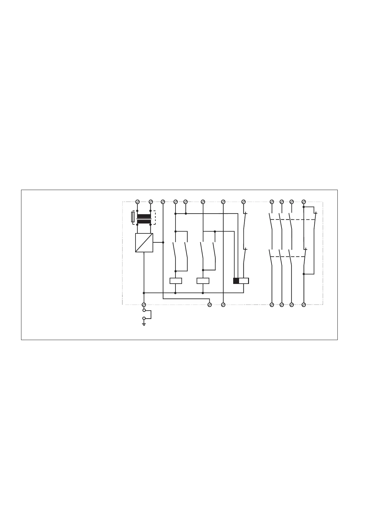
Fig. 1: Innenschaltbild
Internal Wiring Diagram
Schéma de principe
Description du fonctionnement
Le relais PNOZ 1 assure de façon sure,
l’ouverture d’un circuit de sécurité. A la mise
sous tension du relais (A1-A2), si X1-X2 et
T33-T34 sont pontés et les canaux d’entrée
ouverts, le relais K3 colle.
• Fermeture des canaux d’entrée T11, T12
& T22 (par ex. AU non actionné) : les
relais K1 et K2 collent par l’intermédiaire
des contacts K3.1 et K3.2 et
s’automaintiennent par K1.1 et K2.1. Les
LEDs de visualisation sont allumées. Les
contacts de sortie de sécurité (13-14/23-
24 et 33/34) se ferment, le contact
d’information 41-42 s’ouvre.
• Ouverture des canaux d’entrée (par ex.
action sur AU) K1 et K2 retombent. Les
contacts de sortie s’ouvrent de façon
redondante, le contact d’information
41-42 se ferme.
 Loading...