Do you have a question about the Pilz PNOZ 1 and is the answer not in the manual?
| Supply voltage | 24 V DC |
|---|---|
| Category | 4 |
| PL | e |
| SILCL | 3 |
| Rated voltage | 24 V DC |
| Rated current | 6 A |
| Standards | EN 60204-1, EN ISO 13849-1, EN 62061 |
| Weight | 190 g |
The unit may only be installed and operated by personnel familiar with instructions and safety regulations.
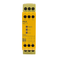
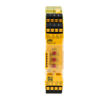
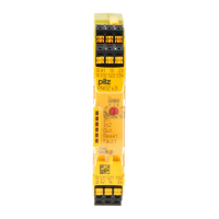
The Safety Relay PNOZ 1 is for Emergency Stop and Safety Circuits according to VDE 0113 and EN 60204-1.
The Safety Relay PNOZ 1 is enclosed in a 90 mm P-97 housing with AC/DC versions.
Explains how the relay provides safety-oriented interruption of a safety circuit.
Details single-channel, two-channel, automatic, and manual reset modes.
Guidance on panel mounting (min. IP54) and DIN-rail attachment for the safety relay.
Notes on output contacts, fuse protection, cable length calculation, and external device connections.
Instructions for applying power, feedback control loop, reset circuit, and input circuit connections.
Procedure for closing the input circuit and manual reset button press.
Describes earth faults, faulty contact functions, and LED indicator issues.
Specifies voltage and current ratings for the input and reset circuits.
Details safety and auxiliary contacts according to EN 954-1 and utilization categories.
Lists switch-on delay, automatic reset, manual reset, and recovery times.
Covers EMC compliance, vibration resistance, climate suitability, and environmental conditions.
Specifies maximum conductor cross-sections for screw terminals.
Provides torque settings for terminals, overall dimensions, and unit weight.
Graph illustrating the service life of output relays based on switching cycles and current.
Device must be installed by persons familiar with instructions and local safety regulations.
The PNOZ 1 safety device is intended for emergency stop and safety circuits.
The PNOZ 1 safety device is housed in a P-97 casing and has various AC/DC versions.
The PNOZ 1 device serves for safety-oriented interruption of a safety circuit.
Describes single-channel, two-channel, automatic and manual reset modes.
The safety relay must be mounted in an electrical cabinet with minimum IP 54 protection.
Pay attention to output contacts, fuse connection, max. line length calculation.
Steps for applying voltage, connecting feedback and reset circuits, and input circuits.
Instructions for closing the input circuit and activating manual reset.
Describes earth faults, faulty contact functions, and LED indicator issues.
Details voltage, tolerance, power consumption, frequency, and input circuit parameters.
Specifies contact configuration, safety categories, and utilization categories.
Information on contact material, external fuse protection, and automatic cut-outs.
Lists max line resistance, response times for automatic/manual reset, and recovery times.
Specifies terminal cross-sections, conductor types, and crimp connector usage.
Provides torque settings for terminals and overall dimensions of the unit.
Graph showing output relay service life based on switching cycles and current.