PNOZ s4.1
Operating Manual PNOZ s4.1
21890-EN-15
| 11
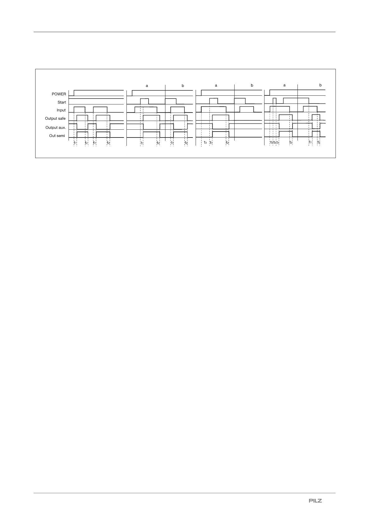
Timing diagram
Legend
} POWER: Supply voltage
} Start: Start circuit
} Input: Input circuit
} Output safe: Safety contacts
} Output aux: Auxiliary contacts
} Out semi: Semiconductor output
} [1]: Automatic start
} [2]: Manual start
} [3]: Monitored start with rising edge
} [4]: Monitored start with falling edge
} a: Input circuit closes before start circuit
} b: Start circuit closes before input circuit
} t
1
: Switch-on delay
} t
2
: Delay-on de-energisation
} t
3
: Waiting period with a monitored start
} t
4
: Min. start pulse duration with a monitored start
Installation
Install base unit without contact expansion module:
} Ensure that the plug terminator is inserted at the side of the unit.
Connect base unit and PNOZsigma contact expansion module:
} Remove the plug terminator at the side of the base unit and at the contact expansion
module.
} Connect the base unit and the contact expansion module to the supplied connector be-
fore mounting the units to the DIN rail.
Installation in control cabinet
} The safety relay should be installed in a control cabinet with a protection type of at least
IP54.
} Use the notch on the rear of the unit to attach it to a DIN rail (35mm).

 Loading...


