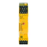
PNOZ s4.1
Operating Manual PNOZ s4.1
21890-EN-15
| 12
} When installed vertically: Secure the unit by using a fixing element (e.g. retaining bracket
or end angle).
} Push the device upwards or downwards before lifting it from the DIN rail.
Wiring
Please note:
} Information given in the "Technical details [ 23]" must be followed.
} Outputs 13-14, 23-24, 33-34 are safety contacts; output 41-42 is an auxiliary contact (e.g.
for display).
} Auxiliary contact 41-42and semiconductor output Y32 should not be used for safety cir-
cuits!
} To prevent contact welding, a fuse should be connected before the output contacts (see
Technical details [ 23]).
} Calculation of the max. cable length l
max
in the input circuit:
R
lmax
= max. overall cable resistance (see Technical details [ 23])
R
l
/km = cable resistance/km
} Use copper wiring with a temperature stability of 75 °C.
} To prevent EMC interferences (particularly common-mode interferences) the measures
described in EN60204-1 must be executed. This includes the separate routing of cables
of the control circuits (input, start and feedback loop) from other cables for energy trans-
mission or the shielding of cables, for example.
} Adequate protection must be provided on all output contacts with capacitive and inductive
loads.
} With U
B
48 – 240 VAC/DC: Connect S21 to the functional earth.
} On 24 VDC devices:
The power supply must comply with the regulations for extra low voltages with protective
electrical separation (SELV, PELV) in accordance with VDE 0100, Part 410.
NOTICE
If you connect contact expansion modules to a base unit with a universal
power supply, you will need to limit the conventional thermal current at the
contact expansion modules' safety contacts to 70% of the stated current
(see technical details for contact expansion module).

 Loading...