PNOZ X7
Operating Manual PNOZ X7
19692-EN-06
10
Installation
} The unit should be installed in a control cabinet with a protection type of at least IP54.
} Use the notch on the rear of the unit to attach it to a DIN rail (35 mm).
} When installed vertically: Secure the unit by using a fixing element (e.g. retaining
bracket or end angle).
Wiring
Please note:
} Information given in the "Technical details [ 14]" must be followed.
} Calculating the max. cable length I
max
in the input circuit on PNOZ X7 24 VAC/DC:
R
lmax
= max. overall cable resistance (see Technical details [ 14])
R
l
/km = cable resistance/km
} Calculating the max. cable length I
max
in the input circuit on PNOZ X7 AC units:
C
lmax
= max. overall line capacitance (see Technical details [ 14])
C
l
/km = line capacitance/km
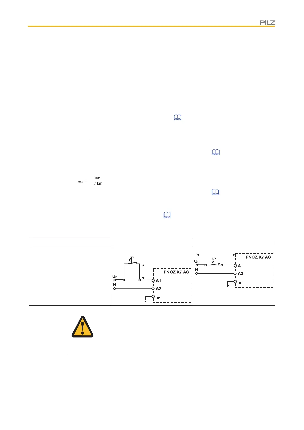
Stub circuit: The max. permitted cable length I
max
depends on the max. overall line ca-
pacitance C
lmax
(see
Technical details [ 14]).
Alternative: Loop circuit: Capacitance is negligible; 1 phase: Max. cable length I
max
: 1
km
Stub circuit Loop circuit
Cable length
WARNING!
If the max. overall line capacitance is exceeded, the unit will no longer
switch off safely and serious injuries and death may result.
Always comply with the max. overall line capacitance.
 Loading...