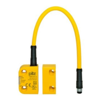
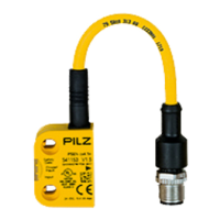
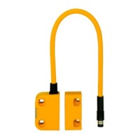
PSEN cs3.1p/M12
Operating Manual PSEN cs3.1p/M12
1003296-EN-09
| 15
Terminal assignment connectors
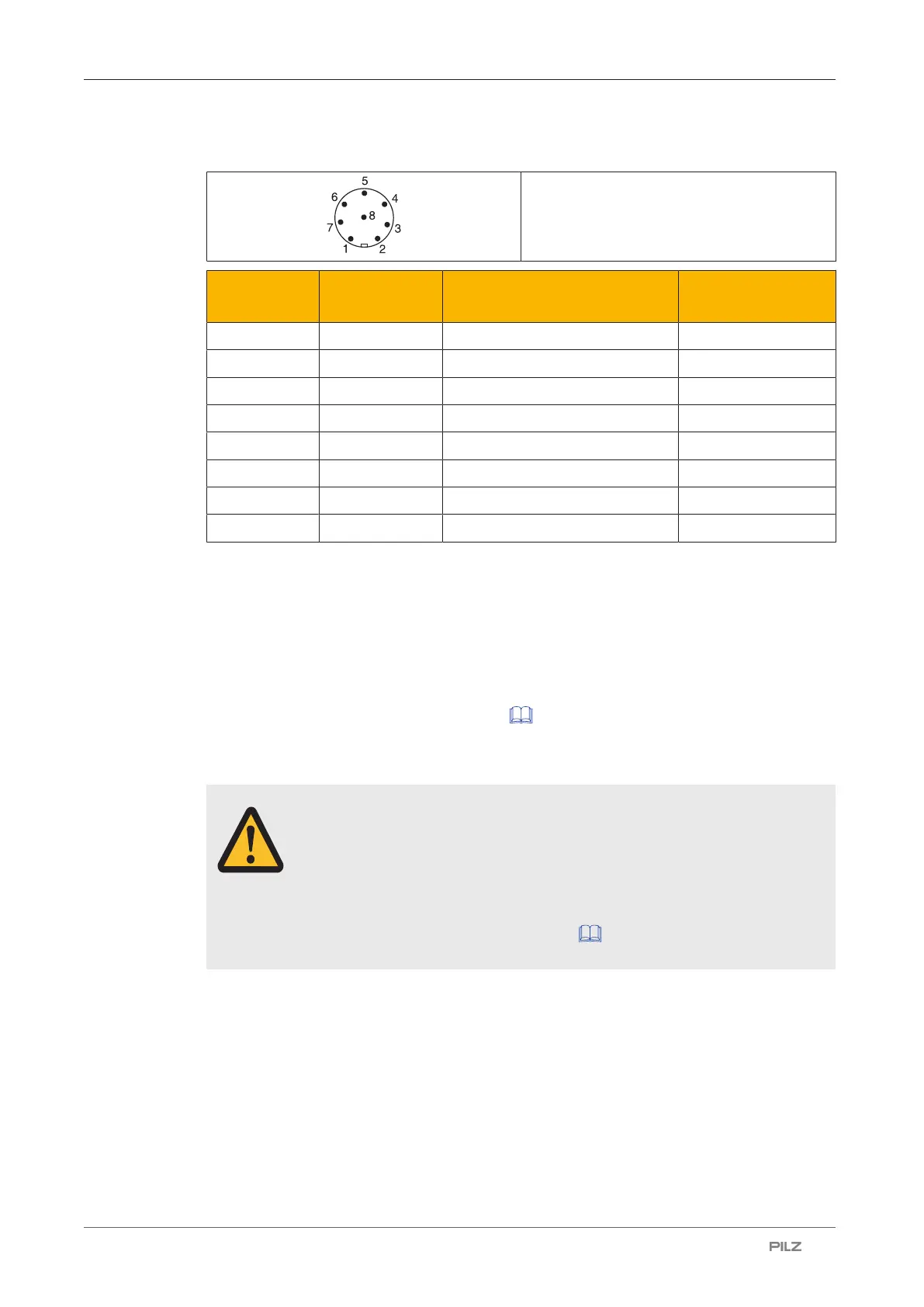
8-pin M8-/ M12-male connector
PIN Connection
designation
Function Wire colour
1 S21 Input, channel 2 white
2 A1 +24 VUB brown
3 12 Output, channel1 green
4 22 Output, channel2 yellow
5 Y32 Signal output/diagnostic output grey
6 S11 Input, channel 1 pink
7 A2 0 V UB blue
8 Y1 Diagnostics input red
The wire colour also applies for the cable available from Pilz as an accessory.
Connection to evaluation devices
Make sure that the selected evaluation device has the following property:
} OSSD signals are evaluated through 2 channels with plausibility monitoring
Please note:
} Information given in the Technical details [ 33] must be followed.
} The use of Safety Device Diagnostics is described in the System Description "Safety
Device Diagnostics".
CAUTION!
Do not connect the signal output to 0 V!
If the signal output Y32 is connected to 0 V, the safety switch may be dam-
aged as a result. Connect the signal output Y32 to a consumer, e.g. to the
input on a control system, or leave the signal output unconnected. Also note
the max. current (see Technical details [ 33]).

 Loading...