PDP-502MX, PDP-502MXE
70
Adjusting Method
Procedure
Adjusting Item Input signal Adjusting Point Adjusting Method
SUB CONTRAST/
SUB BRIGHTNESS
adjustment
SUB VIDEO mode
in Factory mode
SUB CONTRAST
.….
"1" Key
SUB BRIGHT .….
"2" Key
ACL. SW .…. .….
"BS5" Key
Color-difference
Level adjustment
(R–Y LEVEL/
B–Y LEVEL)
REFERENCE 2
in Factory mode
R–Y LEVEL ….….
"BS5" Key
Full Field
Color bar signal
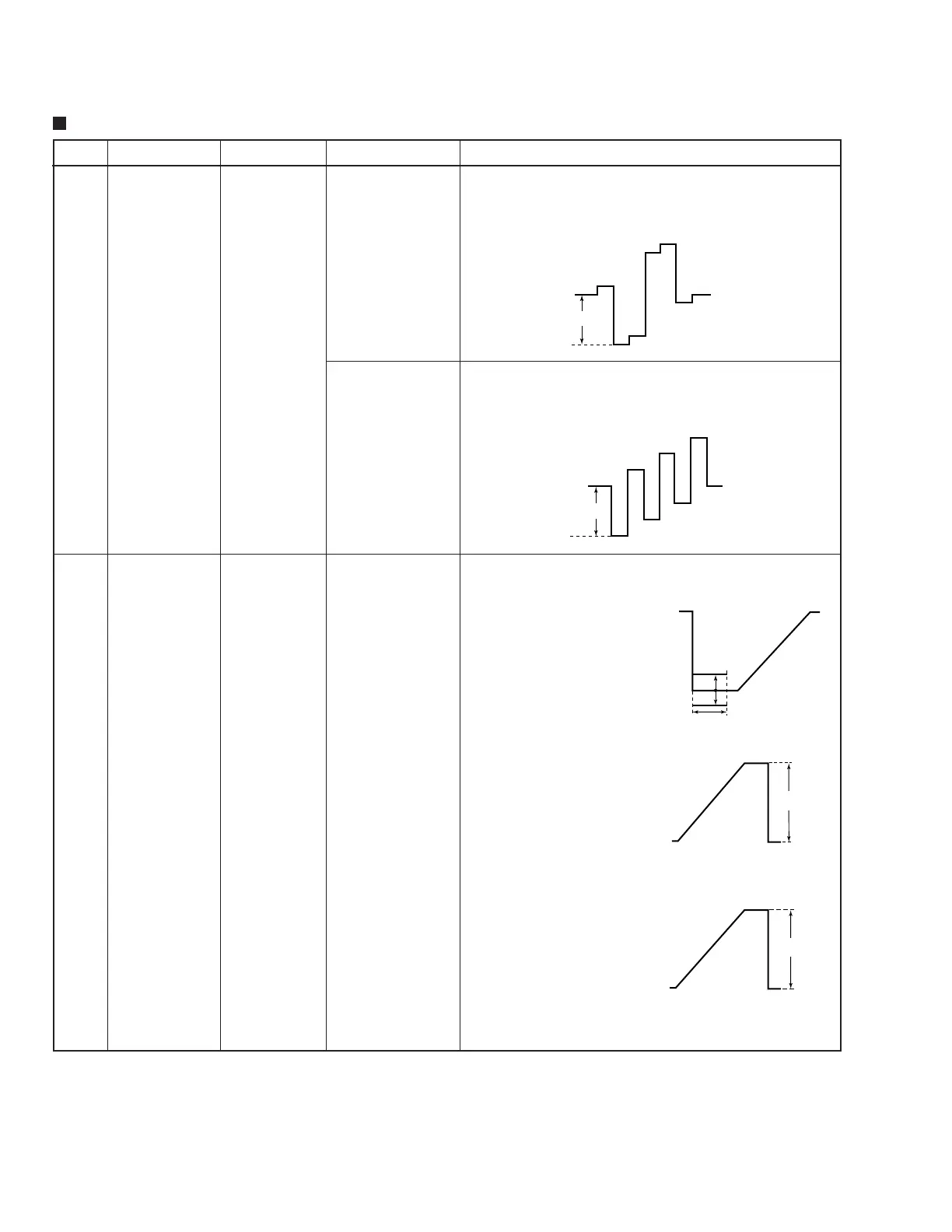
R-Y LEVEL adjustment
Observe R-Y color-difference waveform at Pin 3 (INT_Cr) of IC1401
(MATRIX IC) in VIDEO Assy. Adjust R-Y LEVEL so that the point
indicated in the right figure becomes "260mV±15mV".
260±15 mV
REFERENCE 2
in Factory mode
B–Y LEVEL ….….
"BS7" Key
B-Y LEVEL adjustment
Observe B-Y color-difference waveform at Pin 4 (INT_Cb) of
IC1401(MATRIX IC) in VIDEO Assy. Adjust B-Y LEVEL so that the
point indicated in the right figure becomes "260mV±15mV".
260±15 mV
1) SUB BRIGHT rough adjustment
Set P. ACL. SW OFF.
Observe signal at Pin3 (RED
SIG.) of IC1701(RGB AMP) in
Video Assy. Adjust so that the
blanking period level of the signal
becomes 0 IRE level.
2) SUB CONTRAST adjustment
Set P. ACL. SW OFF.
Adjust so that 0 to 100 IRE level
of the signal at Pin3 (RED SIG.)
of IC1701 (RGB AMP) becomes
"1.1V".
3) SUB BRIGHT fine adjustment
Set P. ACL. SW ON.
Adjust so that the signal level in
blanking period atPin3 (RED
SIG.) of IC1701 (RGB AMP)
becomes 0 IRE level.
4) Signal level (adjustment value)
confirmation
Set P. ACL. SW ON.
Observe the signal at Pin3 (RED
SIG) of IC1701 (RGB AMP) .
Confirm that the 0 IRE to 100 IRE
level of the signal is "0.9V".
RAMP signal
0±20 mV
SUB BRIGHT
Adjustment
H Blanking Period
100 IRE
0 IRE
SUB CONTRAST
Adjustment
1.1±0.02 V
100 IRE
0 IRE
0.9±0.05 V
Signal level (adjustment value)
confirmation
1
2
SUB BRIGHT / SUB CONTRAST adjustment
 Loading...