PDP-502MX
88
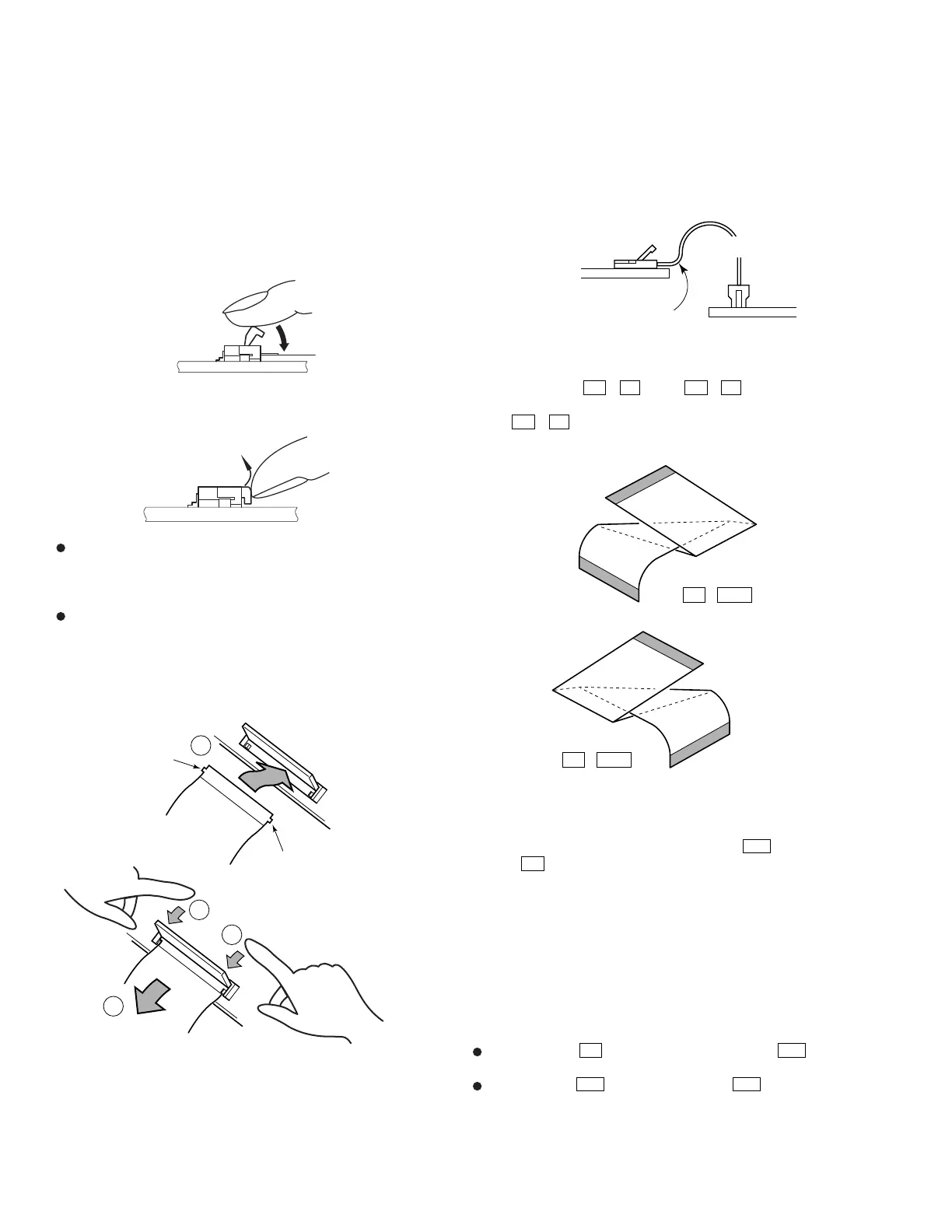
Press-down type lower contact connector
1. Locking
Lock applying force in the arrow direction so that the connector
is pressed down inwards.
2. Unlocking
Push up with your nail, or something soft.
Do not use thin tools such as the tip of screwdrivers, because
they will damage the electrode.
7.1.3 WIRING
Insert the flexible cables straight until the end.
Insert the flexible cable reinforcing plates in parallel to the
connectors. Moreover, insert the horizontal-connecting
connectors horizontally.
In connecting Address Modules and Cable Assy, and in
connecting Scan Modules and Y Drive Assy with the flexible
cables, hook both edges of the flexible cables on the connectors
and fix them, then close the covers.
Insert the flexible cables in parallel to the connector, otherwise
the connectors may be damaged.
Notes
1) Bend the flexible cable between Y Drive Assy and Scan Module
at the Y Drive Assy side, and close the cover.
(To prevent damage of cover)
Moreover, when
H6
–
V4 –1
and
H9
–
V4 –4
flexible cables
are replaced in repair service, be careful of the way of bending.
For
H6
–
V4 –1
flexible cable, be careful that it does not touch
the chassis of FAN.
2) Place the cable between Digital Video Assy
D14
and U-Com
Assy
E5
along the top of Shield Case of Digital Video Assy .
(To prevent noise)
3) Be careful of X Drive Assy and X Cable D Assy / X Cable U
Assy in repair service. Because, they are tightened together
with earth metal fittings being put between X Drive Assy and X
Cable D Assy, X Drive Assy and X Cable U Assy .
4) Be sure to wire between U-Com Assy CN3617 and Digital
Video Assy CN3283 with the grounding solid wire after repair
service.
Others (Attention to mis-wiring )
If U-Com Assy
E5
12pin and Digital Video Assy
D17
12pin
are wired by mistake, the unit will not operate.
If U-Com Assy
E28
6pin and U-Com Assy
E38
6pin are wired
by mistake, the unit will not operate and the temperature sensor
may be damaged. Be sure to check the temperature sensor in the
case of mis-wiring.
When forming the wire cables, be careful not to exert excessive
pressure on the cables as this will result in the disconnection of the
connectors.
J214
H6 – V4–1
J217
H9 – V4–4
Y Drive Assy side
Y Drive Assy side
Scan Module side
Scan Module side
1
2
3
3
Pull it slightly
Hook it on the
connector.
Hook it on the
connector.
Address Module side
Note) When closing the connector cover, press both edges of the
cover by fingers to lock it. Pressing the center of the cover
may damage it.
How to bend the flexible cables
Y Drive Assy side
Scan Module side
Connector
Connector
Frexible Flat Cable
Bend so that the cable is horizontal
to Y Drive connector and then close
the cover.
 Loading...