PDP-502MX
90
E2
CN3603
CN3911
E19
CN3913
E18
CN3921
E17
CN3915
E16
CN3917
E20
CN3611
E22
CN3610
E15
CN3914
E1
CN3755
H3
CN3751
H1
CN3757
CN3801
CN3802
CN3752
H2
H16
H17
H12
D20 D21
D17
CN3402
CN3404
CN3403
D6
CN2301
DIGITAL VIDEO ASSY
UCOM ASSY
AC
INLET
MAIN POWER ASS'Y
CN205
P5
CN354
CN353
P3
P2
CN306
CN355
P6
P4
CN111
P1
P7
CN101
LN
A5
A3
A2
CN302
CN2001
CN2203
A1
A20
CN2202
CN3407
A19
A33
CN3406
CN2901
A34
A17
CN2902
A13
CN3401
INPUT ASSY
VIDEO ASSY
YC SEPA. ASSY
SENS A
FAN 2
FAN 1
FAN 3
FAN 4
FAN 7
FAN 5
FAN 6
POWER
SW
CN3404
CN3618
CN3408
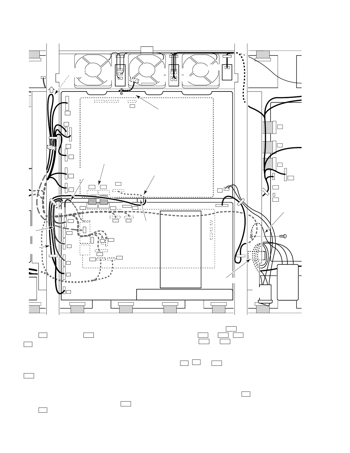
Note 8)
Note 5)
Note 5)
Note 7)
Note 9)
Note 11)
Note 6)
Note 10)
PCB Hihge
Sub Frame L
Pull
Fix the connecting points
with a copper tape
Ferrite Core
5) Do not connect neither ends of the wire between Digital Video
Assy
D6
and Video Assy
A17
to the Assys with connectors.
D6
side …… Bind to chassis of Main Power Assy with a binder
and place it in the open space. At this time, keep
the wires and the connector away from FANs and
each part at the Main Power Assy. Make sure that
the wires and the connector do not touch them.
A17
side…… Pass the hole of Sub Flame L and fix with Wire
Saddle in the open space, then pull the remaining
wires in the arrow direction shown in the upper
figure.
6) Place the wire between Digital Video Assy
D17
and Video
Assy
A3
through the right side of the PCB Hinge.
(To prevent noise)
7) Be careful to handle
A33
side of the coaxial flexible cable
between
A33
and
D20
,
A34
side of the coaxial flexible cable
between
A34
and
D21
. Because they are fixed by soldering.
Moreover, fix the connecting points with a copper tape.
8) Do not pass a band of wires from U-Com Assy to Video Assy
A1
,
A2
and
A19
, through the hole of Sub Flame L. Place
them along the flame and fix with a cable holder.
9) Be sure to wire between U-Com Assy CN3618 and VIDEO
Assy CN3408 with the grounding solid wire after repair service.
10)Connect the housing cable to
A3
with the connector CN2001
at the Video Assy, after passing through the ferrite core on Sub
Flame L.
11)Be sure to confirm the connection of Grounding.
 Loading...