47
VSA-E03
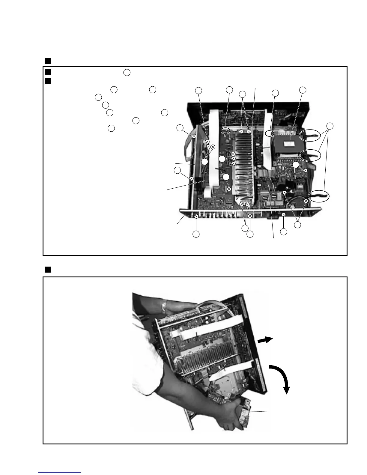
Remove the Bonnet. (seven screws)
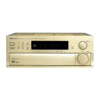
Put the Power Transformer on the bottom side, and stand the component sideways.
Release three binders ( ) from the Power Transformer (T1).
Remove all screws which fixing the Chassis.
1
1
• INPUT Assy (eight screws , Card Spacer )
• DSP Shield (screw )
2 3
4
• Heat Sink (four screws )
5
5
• AMP Assy (three screws , Locking Card Spacer )
6
• Power Transformer (T1) (four screws )
7
8
• Rear Panel (three screws )
9
9
×4
8
×4
Power Transformer (T1)
Power Transformer (T1)
INPUT Assy
Rear Panel
Front
DSP Shield
Heat Sink
AMP Assy
2
2
3
4
2
2
2
5
7
6
6
9
9
1
2
3
4
7. GENERAL INFORMATION
7.1 DISASSEMBLY