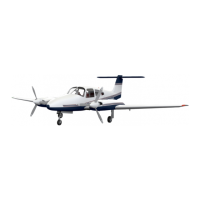
TWIN
COMANCHE
C/R
B.
SYSTEMS OPERATION AND CHECKS
I.
VOLTAGE REGULATING AND ALTERNATOR SYSTEM (FOR AlRCRAFT SER. NOS. 39-l
thru 39-145)
a.
Alternator System
Press-to-test switches, in conjunction with the ammeter, are used to determine the
output of each alternator. These switches are located directly below the ammeter. In the normal
position the ammeter indicates battery charge or discharge current. Depressing an alternator
press-to-test switch causes the ammeter to indicate the output current for the corresponding
alternator, viz. the left switch checks the left alternator.
A preflight check of the alternators should be made during engine run-up. With both
engines operating at approximately 2000 RPM, depress the alternator press-to-test switches
individually and check alternator outputs. These should be approximately equal.
b. Voltage Regulating System
In event of failure of the voltage regulating system an auxiliary regulating system may
be switched into the circuit. Abnormal operation may be indicated by zero output on both
alternator test positions and a discharge indication for battery. To energize the auxiliary
regulating system the following procedure shall be followed:
(1) Reduce aircraft electrical load to minimum for continued safe flight.
(2) Switch “VOLTAGE REGULATOR SELECTOR” to “AUXILIARY” position.
‘(3) Reset tripped breakers but do not reset “MAIN” Voltage Regulator Breaker.
(4) Return to normal required electrical load.
If the electrical system still fails to maintain correct output while using the AUX.
VOLTAGE REGULATOR system, an alternator failure has probably occurred. To isolate the
faulty component the following procedure should be followed:
(1) Reduce aircraft electrical load to minimum for continued safe flight.
(2) Turn aircraft MASTER SWITCH “OFF.”
(3) Place both alternator output circuit breaker switches “OFF.”
(4) Reset both MAIN and AUX. Voltage Regulator Circuit Breakers, if tripped.
Return Voltage Regulator Selector to “MAIN.”
(5) Turn aircraft
MASTER
SWITCH “ON.” Reset Voltage Regulator Circuit Breaker,
if tripped.
(6) Close one alternator output circuit breaker switch. Observe if electrical system is
operating normally by checking for alternator output current on the ammeter. If
not operating properly, open the alternator output circuit breaker; turn aircraft
MASTER SWITCH “OFF” for approximately six seconds to reset the overvoltage
relay.
(7) Turn aircraft MASTER &ITCH “ON.” Reset Voltage Regulator.Circuit Breaker,
if tripped. Close other alternator output circuit breaker switch and observe if
electrical system is operating normally by checking ammeter indication as above.
(8) Check that aircraft electrical load does not exceed the output capability of the
operating alternator causing the battery
to
discharge.
CAUTION
Use of the voltage regulator selector switch and alternator circuit
breakers should be limited to the above conditions.
FAA APPROVED November 28,1969
REISSUED: June 1.1970
REVISED: November 30,197l
REPORT: 1605 PART I PAGE 9
MODEL: PA-39
 Loading...


