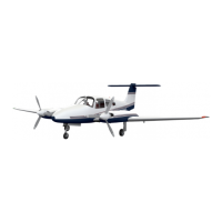
TWIN COMANCHE C/R
FUEL INJECTION
The Bendix RSA-5 fuel injection system is based on the principle of
meaWing
engine air
COnSumptiOn
by use of a venturi tube and using airflow to control fuel flow to the engines. Fuel distribution to the
cylinders in accomplished by a fuel flow divider.
Fuel pressure regulation by means of the servo valve causes a minimal drop in fuel pressure throughout
the metering system. Metering pressure is maintained above vapor forming conditions while fuel inlet
pressure is low enough to allow the use of a diaphragm pump. Vapor lock and associated problems of
difficult starting are thus eliminated.
Incorporated in the servo regulator is the airflow sensing system which contains a throttle valve and
venturi. The differential pressure between the entrance and the throat of the yenturi is the measurement of
air entering the engine. These pressures are applied across an air diaphragm in the regulator. A change in
power changes the airflow to the engine and across the diaphragm in the regulator.
Mounted on top of the engine is the ported fuel flow divider with four nozzle lines routed to the
cylinders. The divider contains a spring loaded positive shut-off valve. Within each cylinder are continuous
flow air bleed nozzles with provisions to eliminate the adverse effects of low manifold pressure when idling.
Since fuel metering is provided by the servo regulator rather than the nozzles, more uniform cylinder head
temperatures result and a longer engine life is possible.
Induction air for the engine enters the opening in the nose cowl and is picked up by a large air duct at
the right rear baffle. The air is directed through a filter and on to the servo regulator. An alternate air
source for the induction system contains a spring loaded door at the throat of the servo regulator. This door
operates automatically if primary source is obstructed or manually by the push-pull control ‘on the right
side of the power control quadrant. The primary.system should always be used for take-off.
‘Q
STRUCTURES
Structures are
of sheet aluminum construction and are designed to ultimate load factors well,,in excess
of
normal requirements.
All components are completely zinc chromate primed and exterior surfaces are
coated with acrylic lacquer.
The main spars of the wings are joined with high strength butt fittings in the center of the’ fuselage,
making in effect a continuous main
spar. The spars are
attached to the fuselage at the side of the fuselage
and in the center of the structure; wings are also attached at the rear
spar and at an auxiliary front spar.
The wing airfoil section is a laminar flow type, with maximum thickness about 40% aft of the leading
edge.
This permits the main spar, located at the point of maximum thickness, to pass through the cabin
under the rear seat, providing unobstructed cabin floor space ahead of the seat.
LANDING GEAR
The nose gear is steerable with the rudder pedals through a 40 degree arc. During retraction of the
gear, the steering mechanism is disconnected automatically to reduce rudder pedal loads in flight. The nose
gear is equipped with a hydraulic shimmy dampener.
Retraction of the landing gear is accomplished through the use of an electric motor and gear tram,
actuating push-pull cables to each of the main gear and a tube to the nose gear. The landing gear motor is
beneath the center floor panel and the selector switch on the instrument panel to the left of the power
control quadrant.
To guard against inadvertent movement of the landing gear selector on the ground, the handle must
also be pulled aft before moving it upward. The gear selector has the shape of a wheel to distinguish it from
the electric flap control which has an airfoil shape. As an added safety feature, the warning horn is
connected to the gear selector switch. The horn will then operate if the selector is moved to the UP position
ARPLANE AND
SYSTEMS
ISSUED: June 1,19X)
PAGE 3
 Loading...


