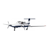
TWIN COMANCHE C/R
overboard. Located inside the fuel valves is a by-pass valve which will open at l/2 psi differential pressure if
the strainer screen becomes blocked.
Fuel quantity is indicated by two electric
gauges located below the instrument cluster. The
instruments are connected to a transmitter unit located in each fuel cell. The gauges will indicate the
amount of fuel available in the cells that are selected.
ELECTRICAL SYSTEM
Electrical power is supplied by two 12 volt 70 ampere alternators and a 35 ampere-hour battery. The
battery is located in the fuselage nose section in a sealed stainless steel battery box. Refer to the
Maintenance Section for servicing of the battery.
There are two voltage regulator systems installed in the Twin Comanche aircraft.
On aircraft up to and including serial number 39-145 the alternators are paralleled by using one
voltage regulator to control field voltage of both alternators. Also incorporated in the system is an
overvoltage relay. Its function is to open and remove field voltage to the unregulated alternators in the
event of a failure of the voltage regulator, thus preventing an overvoltage condition which could damage the
electrical equipment.
In the event of a voltage regulating system failure, an auxiliary regulating system may be switched into
use. Abnormal system operation may be indicated by zero output on both alternator test positions and a
discharge indication for the battery.
NOTE
Use of the Volta& regulator selector switch should be limited to
the above condition unless the Service Manual is consulted.
On aircraft with serial number 39-146 and up, the electrical system incorporates an alternator ’
paralleling system. The system has two voltage regulators which control the alternators. The regulators are
interconnected electrically to provide parallel outputs from their respective alternators under normal
operating engine RPM. Whenever the engines are operating at a hig,h-differential RPM, the alternator
inoperative light for the slower engine may come on.
A distinctive feature of this alternator paralleling system is the split rocker type master switch and the
alternator inoperative lights.
Alternator inoperative lights are located below the ammeter. The lights illuminate when the respective
alternator fails to provide voltage. The lights should be checked prior to starting the engines, to see if the
bulbs are burned out, by turning on the master switch. If the bulbs do not illuminate the bulbs should be
replaced.
NOTE
Refer to the Airplane Flight Manual Section for corrective action
for an alternator failure.
An ammeter, in conjunction with alternator push-to-test switches, is used to check the electrical
system output. All of these items are located on the pilot’s instrument panel. The ammeter normally
indicates battery charge or discharge current. Depressing either of the push-to-test switches will cause the
ammeter to indicate the respective alternator output current.
AIRPLANE AND SYSTEMS
ISSUED: June 1,197O
REVISED: March 30,1973
PAGE 7
 Loading...


