TWIN
COMANCHE C/R
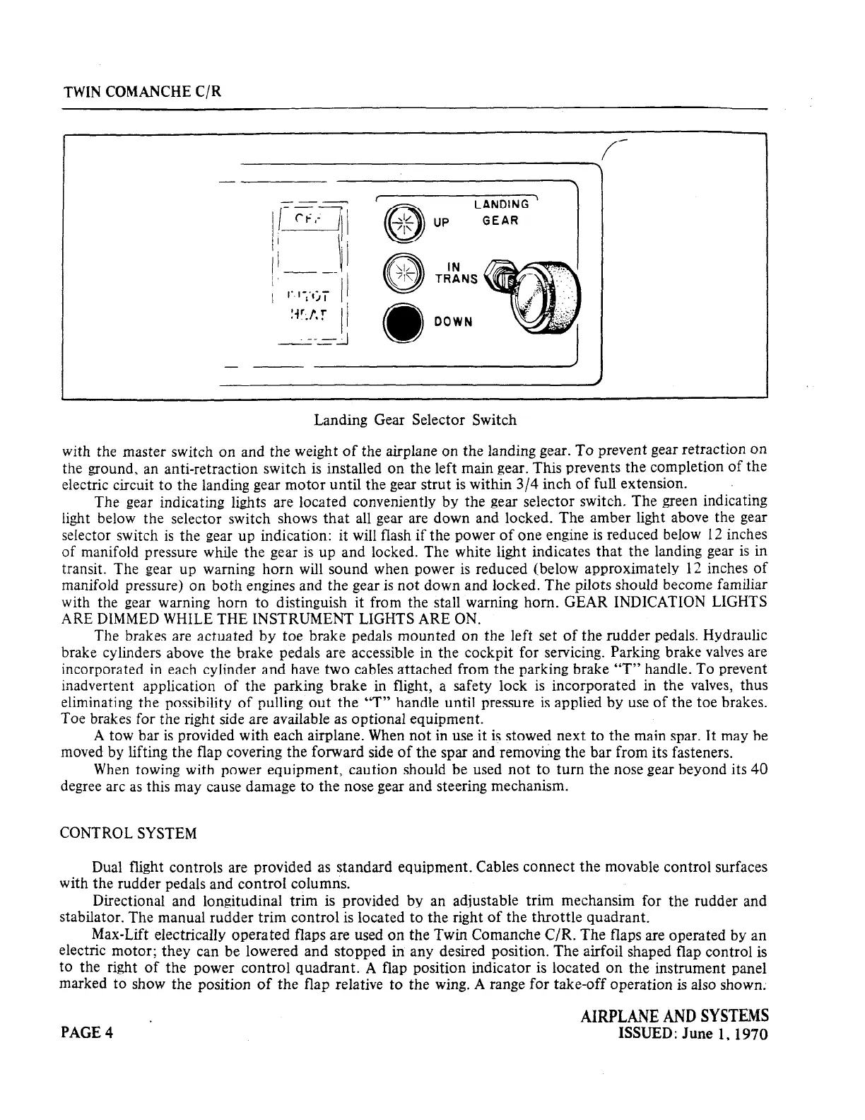
Landing Gear Selector Switch
with the master switch on and the weight of the airplane on the landing gear. To prevent gear retraction on
the ground, an anti-retraction switch is installed on the left main gear. This prevents the completion of the
electric circuit to the landing gear motor until the gear strut is within 3/4 inch of full extension.
.
The gear indicating lights are located conveniently by the gear selector switch. The green indicating
light below the selector switch shows that all gear are down and locked. The amber light above the gear
selector switch is the gear up indication: it will flash if the power of one engine is reduced below 12 inches
of manifold pressure while the gear is up and locked. The white light indicates that the landing gear is in
transit. The gear up warning horn will sound when power is reduced (below approximately 12 inches of
manifold pressure) on both engines and the gear is not down and locked. The pilots should become familiar
with the gear warning horn to distinguish it from the stall warning horn. GEAR INDICATION LIGHTS
ARE DIMMED WHILE THE INSTRUMENT LIGHTS ARE ON.
The brakes are actuated by toe brake pedals mounted on the left set of the rudder pedals. Hydraulic
brake cylinders above the brake pedals are accessible in the cockpit for servicing. Parking brake valves are
incorporated in each cylinder and have two cables attached from the parking brake “T” handle. To prevent
inadvertent application of the parking brake in flight, a safety lock is incorporated in the valves, thus
eliminating the possibility of pulling out the “T” handle until pressure is applied by use of the toe brakes.
Toe brakes for the right side are available as optional equipment.
A tow bar is provided with each airplane. When not in use it is stowed next to the main spar. It may be
moved by lifting the flap covering the forward side of the spar and removing the bar from its fasteners.
When towing with power equipment, caution should be used not to turn the nose gear beyond its 40
degree arc as this may cause damage to the nose gear and steering mechanism.
CONTROL SYSTEM
Dual flight controls are provided as standard equipment. Cables connect the movable control surfaces
with the rudder pedals and control columns.
Directional and longitudinal trim is provided by an adjustable trim mechansim for the rudder and
stabilator. The manual rudder trim control is located to the right of the throttle quadrant.
Max-Lift electrically operated flaps are used on the Twin Comanche C/R. The flaps are operated by an
electric motor; they can be lowered and stopped in any desired position. The airfoil shaped flap control is
to the right of the power control quadrant. A flap position indicator is located on the instrument panel
marked to show the position of the flap relative to the wing. A range for take-off operation is also shown.
PAGE4 .
AIWLANEANDSYSTEMS
ISSUED: June 1,19X)
 Loading...


