EasyManua.ls Logo

Pit Boss PBV3PM1 - Electrical Wire Diagram

Pit Boss PBV3PM1
94 pages
Print Icon
To Next Page IconTo Next Page
To Previous Page IconTo Previous Page
Loading...
ENGLISH
23
 

1.1 /
2.4 /

  
  
  
  
  
  
P
P
R
Y
Y
YP
K
K
W
G
W
W
W
R R
WW
W
W
YY
K
W
  /
  
200, 120, 1.6 
0.375”  5.000”
 
 
120, 60,
0.45 , 1 

 
1, 105°/221°,
183  
 
  
120, 60, 0.45 ,
2  

 
  

 
5 
CONTROL BOARD
  
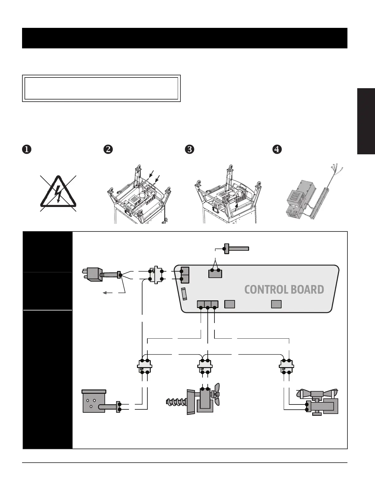
The Control Board system is an intricate and valuable piece of technology. For protection from power surges and electrical shorts,
consult the wire diagram below to ensure your power source is sufficient for the operation of the unit.
   
110120, 60, 250, 3  
: Electrical components, passed by product safety testing and certification services, comply
with a testing tolerance of ± 5-10 percent.
  
  
  .
  
  
 .
 
  
 .
  
   
.

Table of Contents

Related product manuals