INSTALLATION & OPERATIONAL SSHLV MANUAL
8
L20-407 rev.4 (011/16)
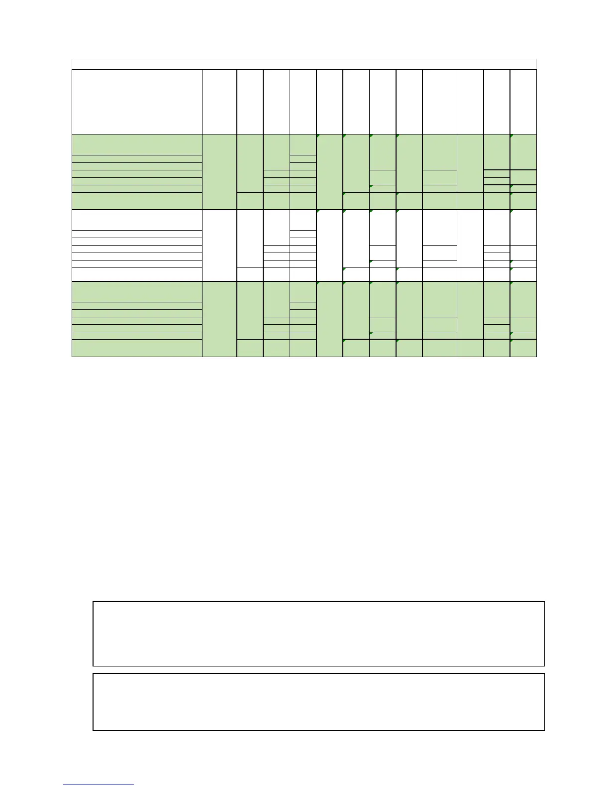
Applicable Countries
Model
Fuel Type
Gas
Appliance
Category
Gross
Input (kW)
Net
Input (kW)
Supply
Pressure (mbar)
Burner
Pressure (mabr)
Burner
Orifice
Pilot
Orifice (code)
Governor
Nominal Gas
Rate (m3/hr)
AT, BG, CH, CZ, DK, EE, FI, GB, GR, HU, IE, IT,
LT, LV, NO, PL, PT, RO, ES, SI, SK, SE, TR
I
2H
LU I
2E
FR I
2ESI
BE G20/G25 I
2E+
NO
DE G20/G25
I
2ELL
YES
NL G25
I
2EK
25 2.15 m m YES 2.3
BG, CH, CY, CZ, FR, DE, GB, GR, HU, IE, IT,
LU, MT, NL, PL, PT, RO, ES, SI, SK, TR
LP G31
I
3P
19.3 50/37 25.4 #56 LP16 YES 0.8
AT, BG, CH, CZ, DK, EE, FI, GB, GR, HU, IE, IT,
LT, LV, NO, PL, PT, RO, ES, SI, SK, SE, TR
I
2H
LU I
2E
FR I
2ESI
B
E G20/G25
I
2E+
NO
DE G20/G25
I
2ELL
YES
NL G25
I
2EK
25 #45 YES 2.3
BG, CH, CY, CZ, FR, DE, GB, GR, HU, IE, IT,
LU
MT
NL
PL
PT
RO
ES
SI
SK
TR
LP G31
I
3P
19.3 50/37 25.4 #56 LP16 YES 0.8
AT, BG, CH, CZ, DK, EE, FI, GB, GR, HU, IE, IT,
LT, LV, NO, PL, PT, RO, ES, SI, SK, SE, TR
I
2H
LU I
2E
FR I
2ESI
BE G20/G25 I
2E+
NO
DE G20/G25
I
2ELL
YES
NL G25
I
2EK
25 2.15 m m YES 2.3
BG, CH, CY, CZ, FR, DE, GB, GR, HU, IE, IT,
LU, MT, NL, PL, PT, RO, ES, SI, SK, TR
LP G31
I
3P
19.3 50/37 25.4 #56 LP16 YES 0.8
SSHLV14
Nat
G20
21
18.9
20
10
1.9 mm
N22
YES
2.0
20/25
1.9/2.15
mm
2.0/2.3
SSHLV14T
Nat
G20
21
18.9
20 1.9 mm
N22
YES 2.0
20/25 1.9m m /#45 2.0/2.3
Nat
G20
21
18.9
20
10
EU GASTECHNICAL INFORMATION
10
1.9 mm
N22
YES
2.0
20/25
1.9/2.15
mm
2.0/2.3
SSHLV184
2.4. GAS CONNECTION
Your gas appliance will give you peak performance when the gas supply line is of sufficient size to
provide the correct gas pressure. The gas line must be installed to meet the local building codes or
National Fuel Gas Code ANSI Z223.1 Latest Edition. In Canada, install the appliance in accordance
with CAN/CGA-B149.1 or .2 and local codes. In Australia, install the appliance in accordance with
AS/NZS 5601. Gas line sizing requirements can be determined by your local gas company or, in North
America, by referring to the National Fuel Gas Code, Appendix C, Table C-4 (for natural gas) and
Table C-16 (for propane). The gas line needs to be large enough to supply the necessary amount of
fuel to all appliances without losing pressure to any appliance.
A properly sized and installed gas line will deliver a supply pressure between 7.0” W.C. (17.4mbars,
1.74kPa) and 10.0” W.C. (24.9mbars, 2.49kPa) natural gas or between 11.0” W.C. (27.4mbars,
2.74kPa) and 13.0” W.C. (32.4mbars, 3.25kPa) for propane to all appliances connected to the supply
line, operating simultaneously at full demand. The pressure at the gas valve shall not exceed ½ PSI
(13.84 “WC, 34.5 mbar, 3.45 kPa). The gas supply connection to this appliance is located in the rear of
the appliance approximately 10-1/2” (26.7 cm) from the floor of the appliance when legs are used.
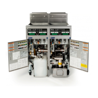
Each appliance is equipped to operate on one certain fuel type. The type of fuel with which the
appliance is intended to operate is stamped on the data plate, which is attached to the inside of the
door.
WARNING
NEVER supply the appliance with a gas other than the one that is indicated on the data
plate. Using the incorrect gas type will cause improper operation and could result in serious
injury or death. If you need to convert the appliance to another type of fuel, contact the
dealer
ou
urchased it from.
NOTICE
NEVER use an adapter to make a smaller gas supply line fit the appliance connection. This
may not allow proper gas flow for optimum burner operation, resulting in poor performance
and improper operation.