ATR 421 - User manual 11
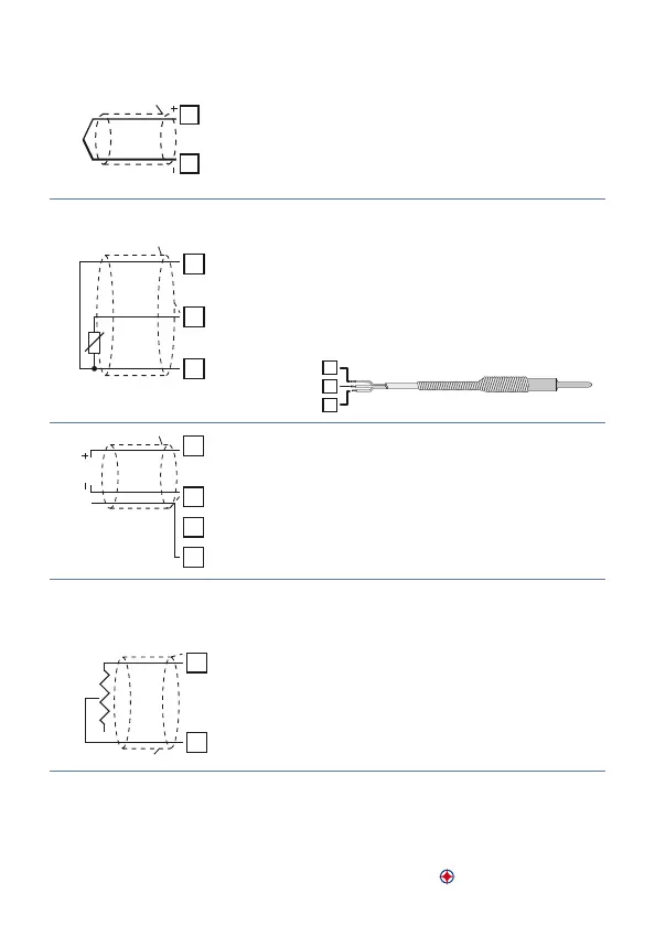
Analogue input AI1
11
12
AI1
TC
Shield/Schermo
For thermocouples K, S, R, J, E, N.
• Comply with polarity
• For extensions make sure to use the correct
extension/compensating cable
• When shielded cable is used, it should be
grounded at one side only.
11
12
13
AI1
Shield/Schermo
PT/NI100
For thermoresistances PT100
• For a three-wires connection use cables with
the same diameter.
• For a two-wires connection short-circuit termi-
nals11 and 13.
• When shielded cable is used, it should be
grounded at one side only.
11
12
13
RED/ROSSO
WHITE/BIANCO
RED/ROSSO
11
12
17
AI1
V
mA
+24V
Shield/Schermo
For linear signals Volt/mA
• Comply with plarity
• When shielded cable is used, it should be
grounded at one side only.
Analogue input AI2
15
16
AI2
FEEDBACK
POT.
Shield/Schermo
For feedback potentiometer on motorized
valves
• Max. resistance 150 KΩ.
• When shielded cable is used, it should be
grounded at one side only.