6 - HMI Series - User manual
2 Device installation
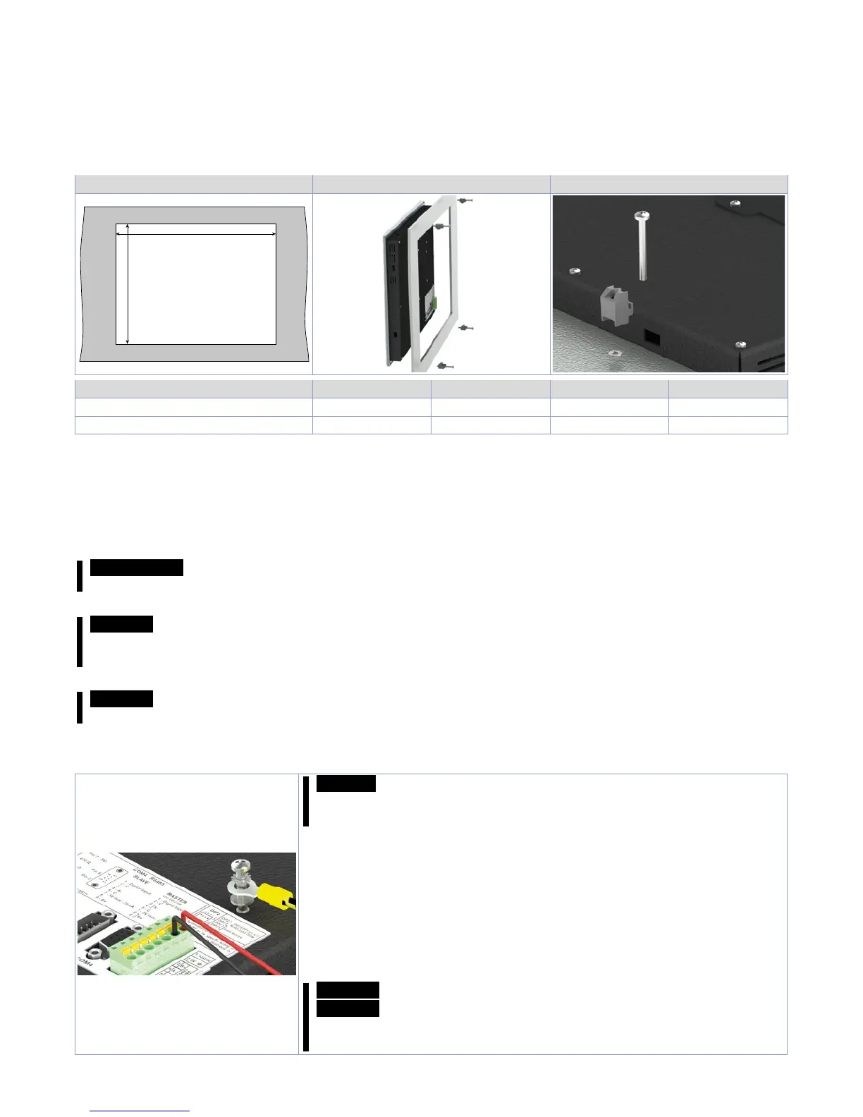
The device panel is installed in the cutout using provided plastic hooks. The number of provided
plastic hooks depends on the panel. The thickness of the wall or cabinet plate must be between 1 mm
and 5 mm. An ISO 7045 (ex UNI 7687 DIN 7985A) Phillips screwdriver is needed to tighten and loosen
the screws on the retaining clips. The maximum tightening torque for the retaining clips is 0,5 Nm.
Devices must be installed on a flat, clean and burr-free surface; uneven areas can cause damage to
the display when the screws are tightened or the intrusion of dust and water. (as per figures 1 and 2)
Cut-out Fig. 1 Fig. 2
L (± 0,5 mm)
H (± 0,5 mm)
TD410 TD710 TD810 TD820
External dimensions (mm) 140 x 100 x 29 204 x 160 x 35 274 x 216 x 35 317 x 256 x 35
Cut-out (mm) 132 x 90 181 x 144 259 x 202 302 x 242
2.1 Spacing for air circulation and ventilation
In order to guarantee sufficient air circulation, allow 5cm of empty space above, below, to the side
and behind the device. No other ventilation system is required. The HMI device is self-ventilated and
approved for inclined mounting at angles up to ±35°in stationary cabinets.
Information! If additional space is needed to operate or maintain the device, this must be taken into
consideration during installation.
Caution! The spacing specifications for air circulation are based on the worst-case scenario for
operation at the maximum specified ambient temperature. The maximum specified ambient
temperature must not be exceeded!
Caution! An inclined installation reduces the convection by the HMI device and therefore the
maximum permissible ambient temperature for operation.
3 Power supply and grounding
Danger! This device is only permitted to by supplied by a SELV /
PELV (class 2) power supply or with safety extra-low voltage (SELV)
in accordance with EN 60950.
Connect a 24VDC 1,0A (min.) power supply, as showed into the figure.
Connect the device grounding with a conductor of 18AWG (2,5mmq)
minimum section. For the whole series it is suggested to use a 24
VDC 1,0A 24VA power supply (Pixsys code 2700.10.008).
Use Copper, Copper-Clad Aluminium or Aluminium conductors wire
for all electric connection.
Caution!
24VDC power supply line must be protected by a 1,0A fuse.
Caution! Functional ground must be kept as short as possible and
connected to the largest possible wire cross section at the central
grounding point (e.g. the control cabinet or system).