8 - HMI Series - User manual
6.1 CANopen
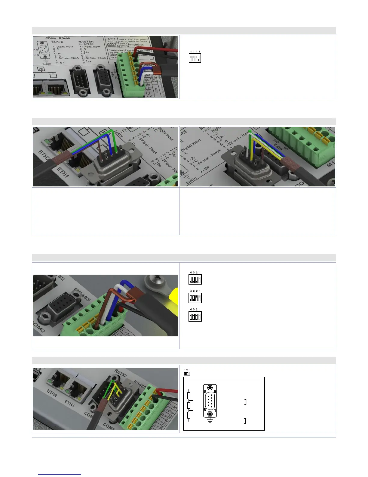
6.1.a Using CAN / EXP1 on terminal M1
DIP2
OFFON
EXP1/CAN with termination resistor 120Ω
EXP1/CAN con terminazione 120Ω
PIN5: GND (brown)
PIN6: CANH (blue)
PIN7: CANL (white)
6.2 RS232
6.2.a Using RS232 / COM1 on DB9 (No available for TD410)
Standard RS232 connection:
PIN2: RX (green)
PIN3: TX (blue)
PIN5: GND (brown)
RS232 connection with RTS / CTS:
PIN2: RX (green)
PIN3: TX (blue)
PIN5: GND (brown)
PIN7: RTS (white)
PIN8: CTS (yellow)
6.3 RS485
6.3.a Using RS485 / COM2 on terminal M1
OFFON
RS485 MASTER:
Polarization only 470Ω
Solo polarizzatore 470Ω
OFFON
RS485 MASTER:
Termination 330Ω Polarization 470Ω
Terminatore 330Ω Polarizzatore 470Ω
OFFON
RS485 SLAVE
PIN3: B+ (green)
PIN4: A- (yellow)
PIN5: GND (brown)
6.3.b Using RS485 / COM2* MASTER on DB9 (No available for TD410)
1
5
9
6
COM2 RS485
EARTH
Pin 5 : C
Pin 8
Pin 7 : 5Vi
Pin 3
470 Ω
470 Ω
330 Ω
B+
A-
MASTER
1 - Input
2 - C
3
4
5 - C
7 - 5V
8
9
Note: 5V Is isolated an can supply 70mA max
OFFON
DIP2 2,3,4 to off
DIP2
* Using the DB9 connector it is possible to introduce termination resistances using DIP2 as for terminal M1 or short-circuiting terminals 3-4 e 8-9, as showed
in the figure.