EasyManuals Logo

Pixsys PL260 User Manual

Pixsys PL260
72 pages
To Next Page IconTo Next Page
To Previous Page IconTo Previous Page
Page #13 background imageLoading...
Page #13 background image
13
1.5.3 Connection of a load cell
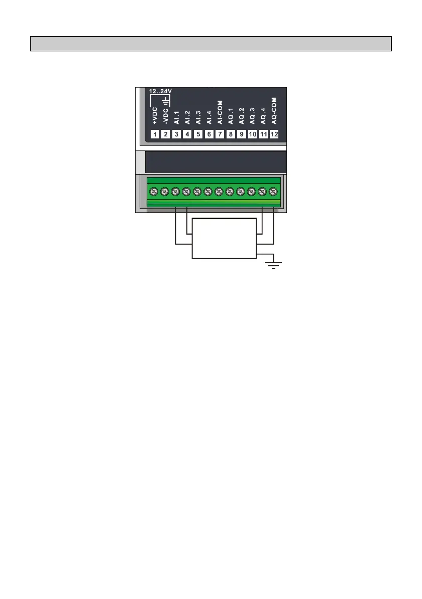
Below some examples of connection for a load cell to the analogue inputs of
PL260.
Weight Cell
SIGNAL
-
+
SUPPLY
+
-
SHIELD
As showed in the figure, to connect a load cell to the PL260 it is necessary to:
Create the voltage (max 5 Vdc) to supply the cell through the analogue
output AQ4.
Connect the load cell signals + and – to the analogue inputs AI1 (signal +)
and AI2 (signal -) for reading the differential voltage generated.
Configure the reference to convert input AI1 on AI2 (SM82 = 2).
Configure analogue input AI1 on 0..20 mV (SM40 = 4).

Table of Contents

Questions and Answers:

Question and Answer IconNeed help?

Do you have a question about the Pixsys PL260 and is the answer not in the manual?

Pixsys PL260 Specifications

General IconGeneral
BrandPixsys
ModelPL260
CategoryController
LanguageEnglish

Related product manuals