18
1.6.3 Setting dip-switch to select analogue intput AI5..6
Analogue inputs AI5..AI6 are generally selected (reset setting) through
SMW44 and SMW45 as "Disabled". They can be configured as 0..10V 10 bit
only if inputs AI1 and AI2 have not yet been selected as 0..10V 10 bit. AI5
uses part of the hardware of AI1, while AI6 uses part of the hardware of AI2.
Selecting inputs AI5 and AI6 as 0..10V 10 bit through the relative dip-switch
(see following figures), signal applied to input I7 is converted to analogue, the
read value is deducted and assigned to AI5; the signal applied to input I8 is
converted to analogue, the read value is deducted and assigned to input AI6.
In this way it is possible to obtain two inputs 0..10V in addition to the 4
universal analogue inputs.
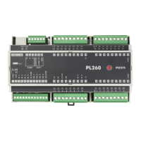
Figures below show the settings for dip-switch to configure analogue input
AI5.
Disabled
Analogue input AI5 is disabled
and input I7 is used as digital
input.
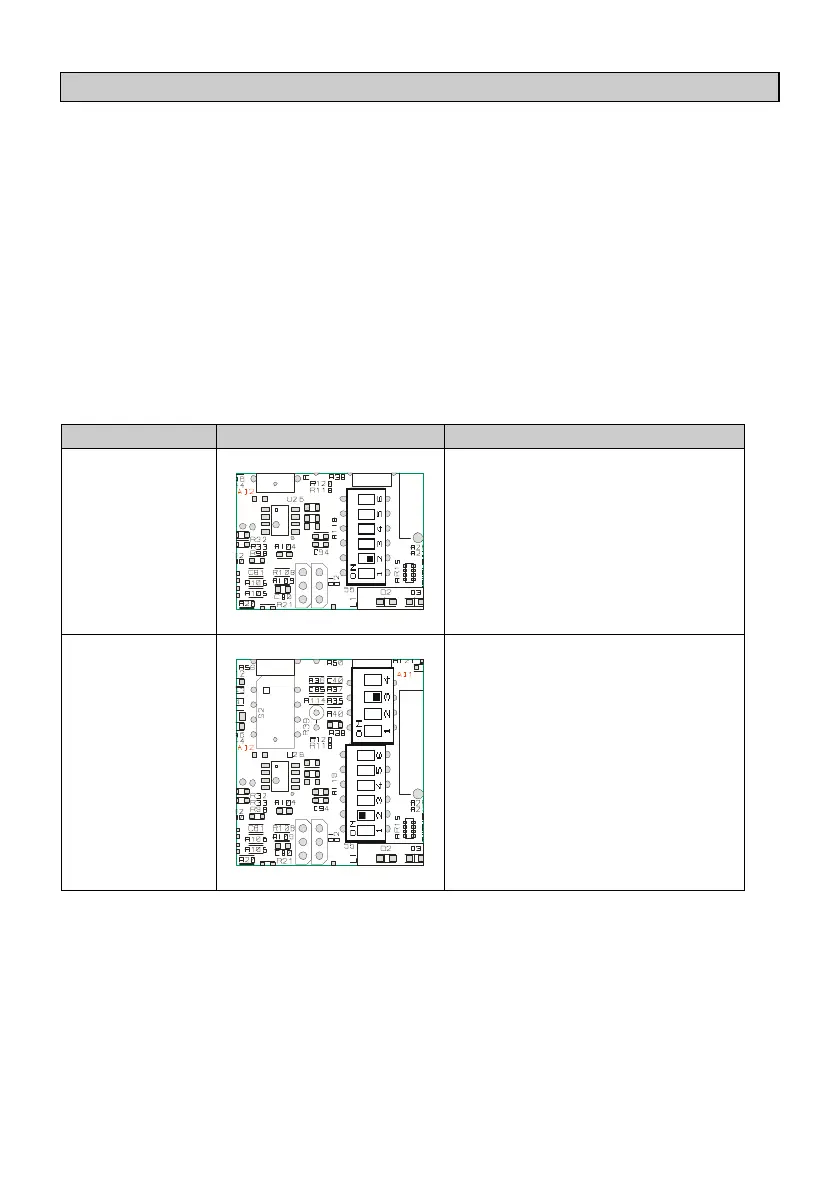
0..10V 10 bit
Connect positive signal to
digital input I7, and the
reference signal to pin -VDC
(2).