16
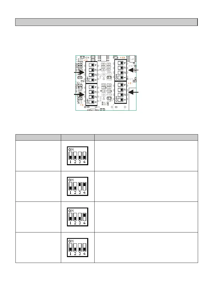
1.6.2 Setting dip-switch to select analogue input AI1..4
Each analogue input can be configured through a 4 way dip-switch, the
correspondence between the inputs and the relative dip-switch is showed in
the figure below:
AI1
AI3
AI2
AI4
To obtain the required input type, it is necessary to set the relative dip-switch
as indicated in the table below:
Disabled
If the analogue input is not used, leave all
switches off as showed in the figure.
0..10V 10 bit
Connect the positive signal to the analogue
input, and the reference signal to the pin
AI-COM.
0..10V 16 bit
Connect the positive signal to the analogue
input, and the reference signal to the pin
AI-COM.
0..1V
0..20 mV
Connect the positive signal to the analogue
input, and the reference signal to the pin
AI-COM.