9
1.5 Electrical wiring
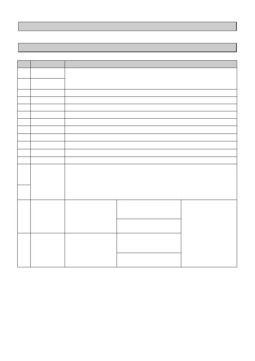
1.5.1 Connectors and terminal blocks
1 +
Power-supply 12÷24V DC 6VA. To improve noise immunity,
the use of a dedicated supply is recommended.
2 -
Analogue input AI1 positive signal
Analogue input AI2 positive signal
Analogue input AI3 positive signal
Analogue input AI4 positive signal
Common negative signal for analogue inputs
8 AQ.1
Analogue output AQ1 positive signal (0÷10 VDC)
9 AQ.2
Analogue output AQ2 positive signal (0÷10V DC)
10
AQ.3
Analogue output AQ3 positive signal (0÷12,5 VDC)
11
AQ.4
Analogue output AQ4 positive signal (0÷12,5 VDC)
Common negative signal for analogue outputs
21
+V
Common positive signal for digital inputs. Connect this signal
to one of the digital inputs I1÷I16, to activate inputs. Voltage
available on these pins can supply sensors to connect to the
analogue inputs (N.B.: on these pins the available supply is
Vcc, not stabilized!).
45
13
I1 / A1
Digital input
PL260-11AD: input for
bidirectional encoder no.
1 (phase A)
To activate digital
inputs, short-circuit
signal +V on the
input pin.
PL260-12AD: input for
fast counter no. 1
14
I2 / B1
Digital input
PL260-11AD: input for
bidirectional encoder no.
1 (phase B)
PL260-12AD: input for
fast counter no. 2