6
3. Wiring the Power Inputs
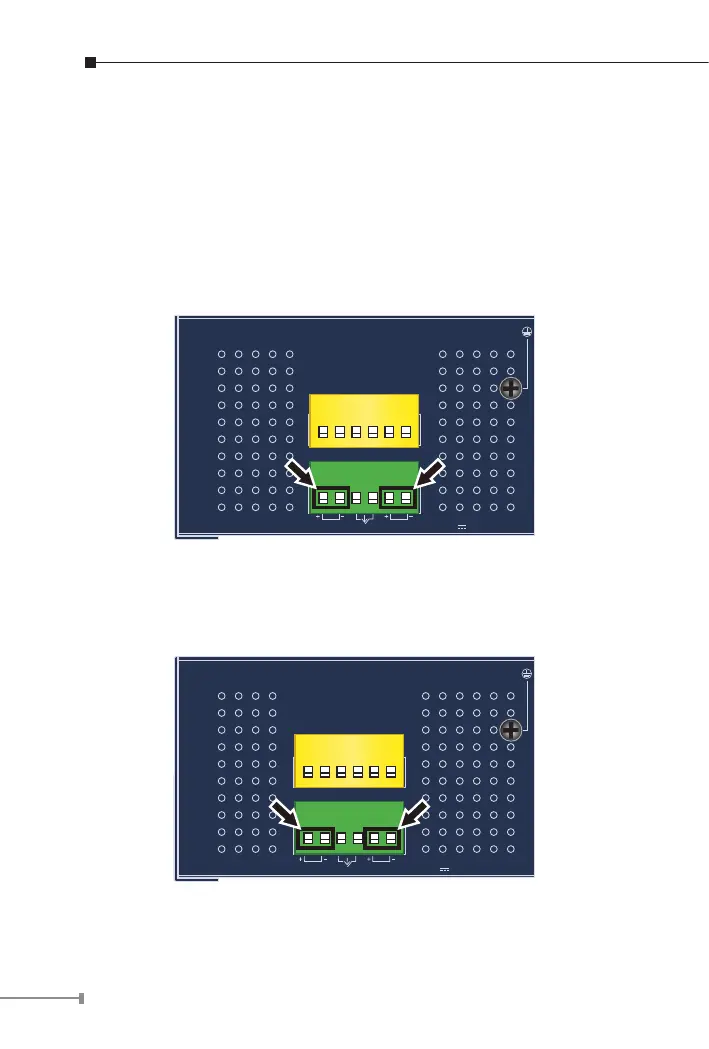
The Upper Panel of the Industrial Managed Switch comes with a DC
inlet power socket and one 6-contact terminal block. Please follow the
steps below to insert the power wire.
1. Insert positive/negative DC power wires into Contacts 1 and 2 for
Power 1, or Contacts 5 and 6 for Power 2.
IGS-5225-8P4S/IGS-5225-8P2T2S/IGS-5225-8P2T4S: DC 48~56V
PWR1
PWR2
Alarm
DI1 DO0 DO1DI0 GNDGND
DC Input:
48-56V , 6A max.
Max. Fault Alarm Loading: 24V, 1A
1 2 3 4 5 6
1 2 3 4 5 6
Figure 3-1: IGS-5225-8P4S/IGS-5225-8P2T2S/IGS-5225-8P2T4S Upper Panel
IGS-5225-4UP1T2S: DC 48~56V
PWR1
PWR2
Fault
DI1 DO0 DO1DI0 GNDGND
DC Input:
48-56V , 6A max.
Max. fault loading: 24V, 1A
1 2 3 4 5 6
1 2 3 4 5 6
Figure 3-2: IGS-5225-4UP1T2S Upper Panel
 Loading...