11
Step 2: The PSE delivers both Ethernet Data and PoE power over UTP cable
to the Industrial PoE Extender and the “PoE IN” LED will be lit
steadily.
1. When the LED turns steady amber, it means the Industrial
PoE Extender is being powered successfully with PoE.
2. If the LED is not lit, please check whether the remote PSE
or the cable is connected to a PC or a network device, or
the use of cable is correct or not. If not, check whether the
power injection going to a PD is correct or not.
3. Never connect any non-standard PoE PSE to the Industrial
PoE Extender; it will damage the device permanently.
4. Refer to Chapter 2.2 for more information about LED function.
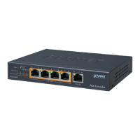
3.5 Connecting WGS-E304PT to PD
Step 1: Connect the additional Cat5e/6 cable from the PoE+ Out of the
Industrial PoE Extender to a remote PD.
PoE
PD
802.3at/802.3af PoE output
WGS-E304PT
PoE
++
PD 802.3at PoE
+
Extender
5
4
3
2
1
VLAN
ExtendStandard
ACTLNK
PoE-in-Use
ACTLNK
PoE IN
WGS-E304PT
PoE
++
PD 802.3at PoE
+
Extender
5
4
3
2
1
VLAN
ExtendStandard
ACTLNK
PoE-in-Use
ACTLNK
PoE IN
Step 2: The PoE+ Out port is also the power injector, which transmits
DC voltage to the Cat5e/6 cable and transfers data and power
simultaneously between the PSE and PD.