Page 38
APPENDIX B
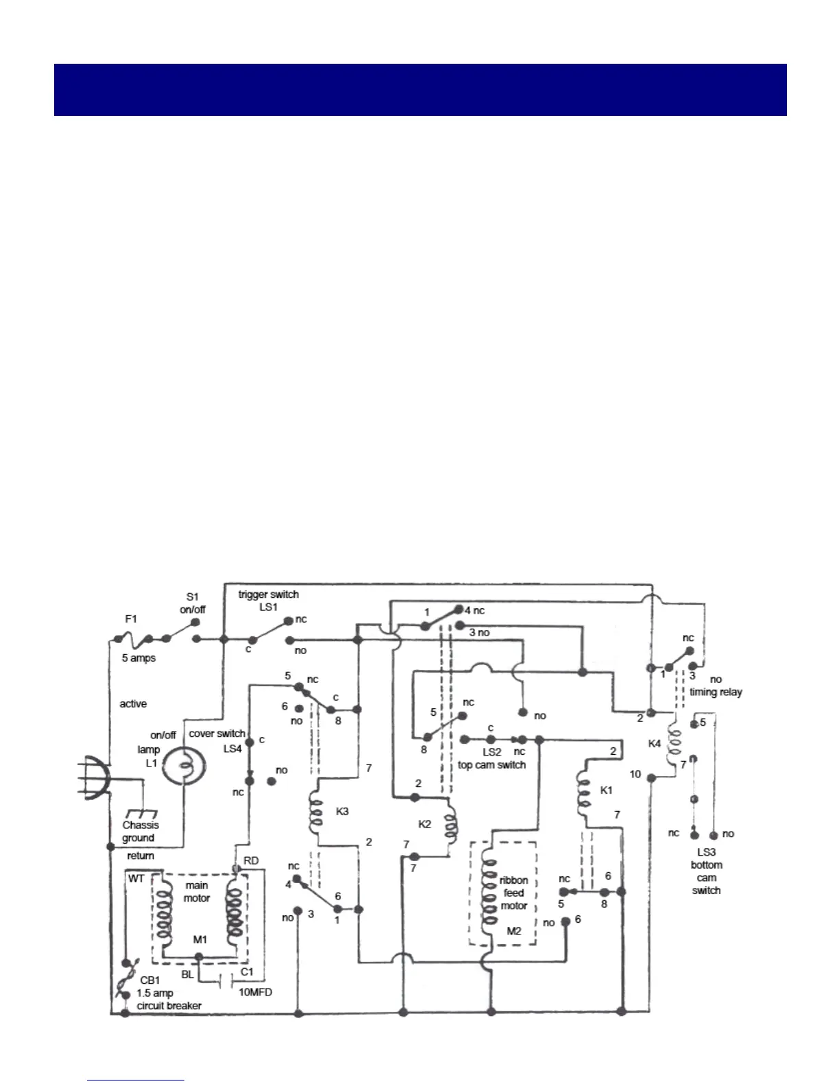
ELECTRICAL SYSTEM FUNCTIONS
Schematic illustrates condition of all switches when the XL2 is at rest (in between tying cycles)
with cover closed (LS4 closed).
When the product to be tied is inserted into the tying area, Trigger Switch (LS1) closes and acti-
vates the main motor and cam. As the main motor and cam begin to turn, the cam closes top and
bottom cam switches (LS2 & LS3) activating relays (K2 & K4).
Then, when the main motor and cam finish one complete rotation, the cam switches are reo-
pened causing three effects:
1.Relays (K1 & K#) are activated, disabling the main motor and cam.
2.Timing relay (K4) begin its delay cycle.
3.The ribbon feed motor begins to turn.
When timing relay (K4) times out (depending on the setting of the “Tying adjustment Dial”), all
relays deactivate, the ribbon feed motor shuts off, and the unit is once again at rest.
 Loading...