5.0/5.7/6.0L/8.1L General Information 1 - 11
MEFI 4 - PCM
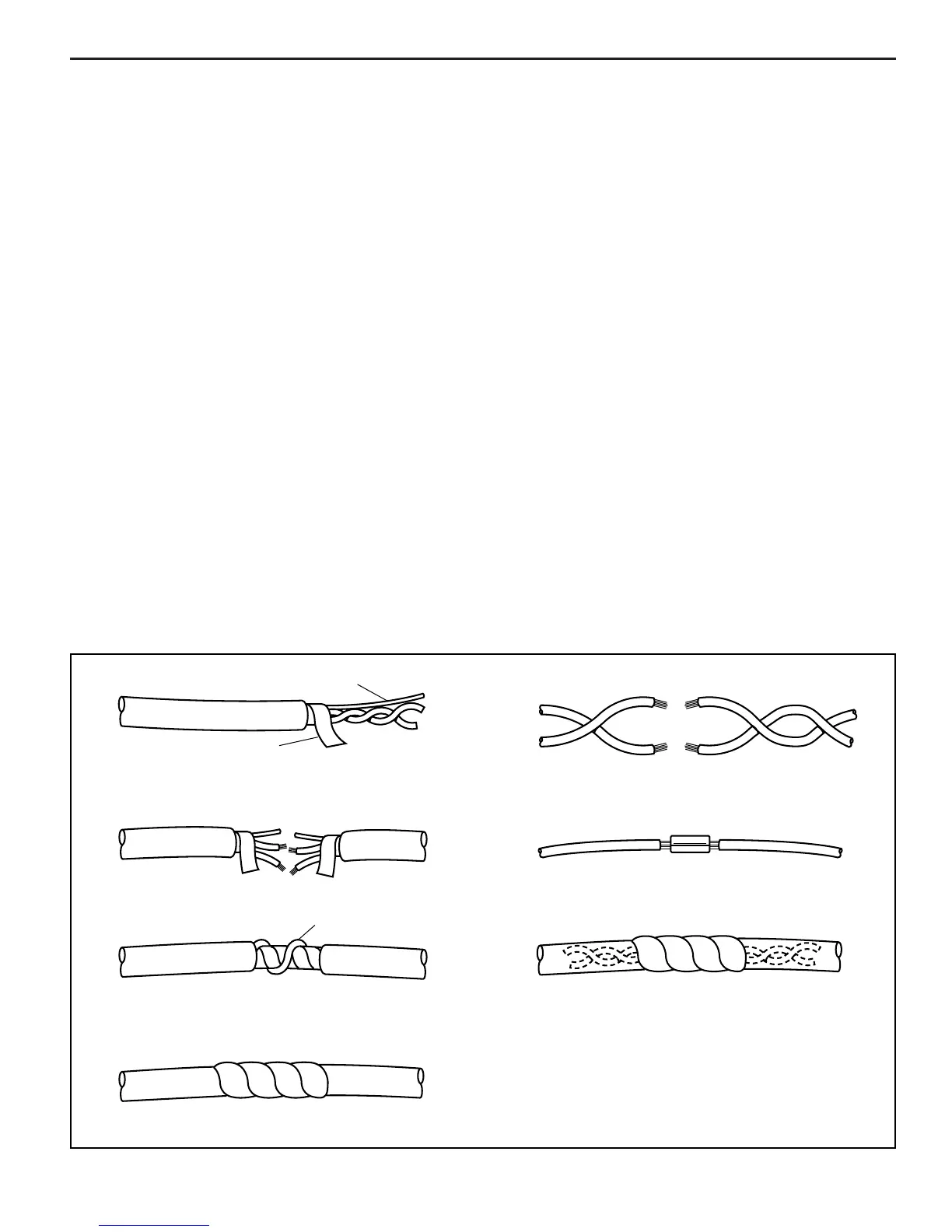
OUTER JACKET
MYLAR
DRAIN WIRE
DRAIN WIRE
1REMOVE OUTER JACKET.
2UNWRAP ALUMINUM/MYLAR TAPE. DO NOT
REMOVE MYLAR.
1LOCATE DAMAGED WIRE.
2REMOVE INSULATION AS REQUIRED.
3SPLICE TWO WIRES TOGETHER USING SPLICE
CLIPS AND ROSIN CORE SOLDER.
3UNTWIST CONDUCTORS. STRIP INSULATION AS
NECESSARY.
6TAPE OVER WHOLE BUNDLE TO SECURE AS BEFORE.
4SPLICE WIRES USING SPLICE CLIPS AND ROSIN CORE
SOLDER. WRAP EACH SPLICE TO INSULATE.
5WRAP WITH MYLAR AND DRAIN (UNINSULATED) WIRE.
4COVER SPLICE WITH TAPE TO INSULATE
FROM OTHER WIRES.
5RETWIST AS BEFORE AND TAPE WITH
ELECTRICAL TAPE AND HOLD IN PLACE.
8-24-94
RS 22186
Figure 1-5 - Wiring Harness Repair
•
Tendency for connectors to come apart due to vibration
and/or temperature cycling.
•
Terminals not fully seated in the connector body.
•
Inadequate terminal crimps to the wire.
On-Board Service
Wiring Harness Service
Figure 1-5
Wiring harnesses should be replaced with proper part
number harnesses. When wires are spliced into a harness,
use the same gauge wire with high temperature insulation
only.
With the low current and voltage levels found in the
system, it is important that the best possible bond be
made at all wire splices by soldering the splices as shown
in Figure 1-5.
Use care when probing a connector or replacing a connector
terminal. It is possible to short between opposite terminals.
If this happens, certain components can be damaged.
Always use jumper wires with the corresponding mating
terminals between connectors for circuit checking. NEVER
probe through connector seals, wire insulation, secondary
ignition wires, boots, nipples or covers. Microscopic
damage or holes may result in water intrusion, corrosion
and/or component failure.
Diagnosis
The diagnostic tables and functional checks in this manual
are designed to locate a faulty circuit or component through
logic based on the process of elimination. The tables are
prepared with the requirement that the system functioned
correctly at the time of assembly and that there are no
multiple failures.
Engine control circuits contain many special design features
not found in standard vehicle wiring. Environmental
protection is used extensively to protect electrical contacts.
Proper splicing methods must be used when necessary.
The proper operation of low amperage input/output circuits
depend upon good continuity between circuit connectors. It
is important before component replacement and/or during
normal troubleshooting procedures that a visual inspection
of any questionable mating connector is performed. Mating
surfaces should be properly formed, clean and likely to
make proper contact. Some typical causes of connector
problems are listed below:
•
Improperly formed contacts and/or connector
housing.
•
Damaged contacts or housing due to improper
engagement.
•
Corrosion, sealer or other contaminants on the contact
mating surfaces.
•
Incomplete mating of the connector halves during
initial assembly or during subsequent troubleshooting
procedures.
 Loading...