2 - 4 ECM and Sensors 5.0/5.7/6.0/8.1L
MEFI 4 - PCM
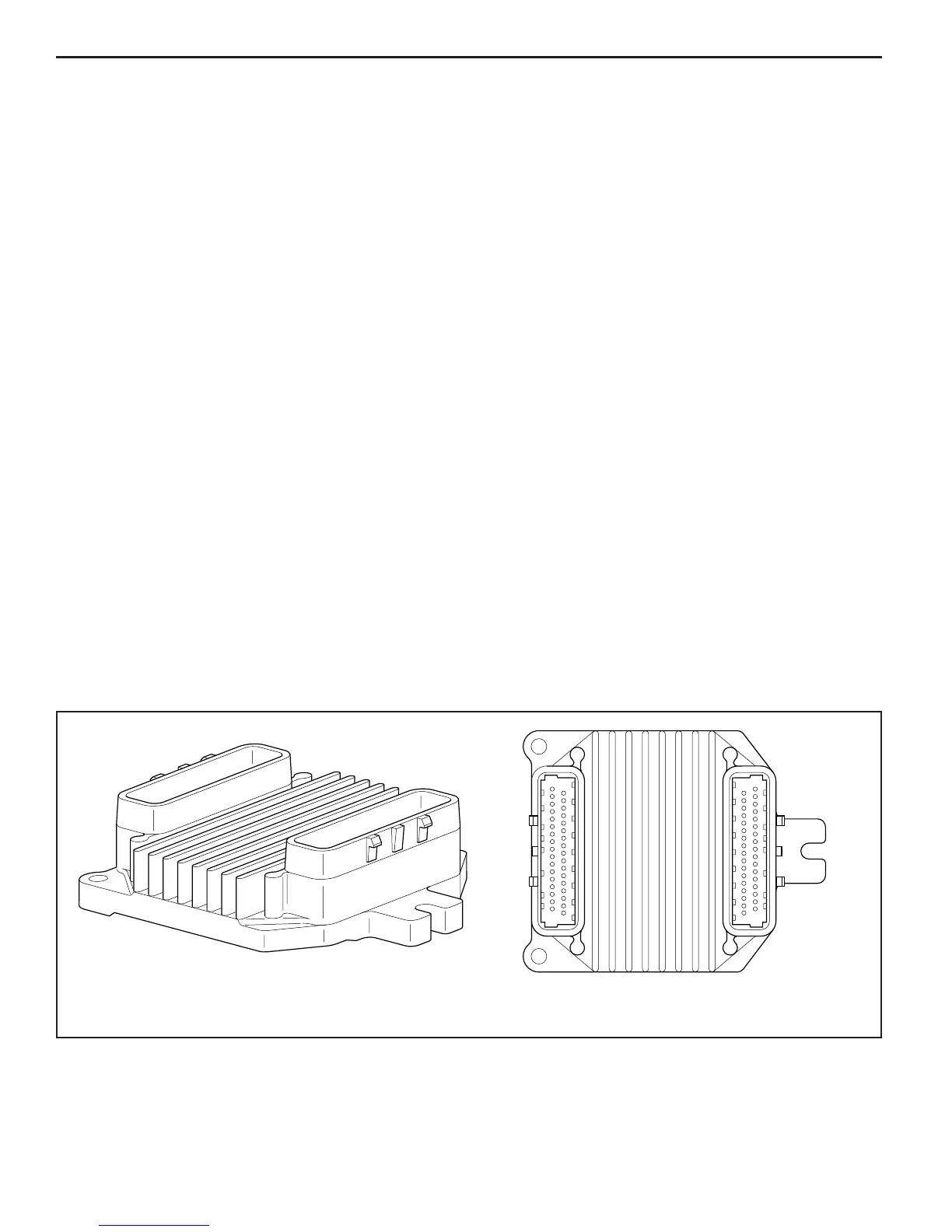
J2J1
MEFI3004
Figure 2-4 - Engine Control Module (ECM)
The ECM controls output circuits such as the injectors,
IAC, relays, etc. by controlling the ground or power feed
circuit.
Memory
There are three types of memory storage within the ECM.
They are ROM, RAM and EEPROM.
ROM
Read Only Memory (ROM) is a permanent memory that is
physically soldered to the circuit boards within the ECM.
The ROM contains the overall control programs. Once
the ROM is programmed, it cannot be changed. The ROM
memory is non-erasable, and does not need power to
be retained.
RAM
Random Access Memory (RAM) is the microprocessor
“scratch pad.” The processor can write into, or read from
this memory as needed. This memory is erasable and
needs a constant supply of voltage to be retained. If the
voltage is lost, the memory is lost.
EEPROM
The Electronically Erasable Programmable Read Only
Memory (EEPROM) is a permanent memory that is
physically soldered within the ECM. The EEPROM contains
program and calibration information that the ECM needs
to control engine operation.
The EEPROM is not replaceable. If the ECM is replaced,
the new ECM will need to be programmed by the engine
manufacturer with the calibration information that is specifi c
to each marine application.
Engine Control Module (ECM)
The Engine Control Module (ECM), located on the engine,
is the control center of the fuel injection system. It controls
the following:
• Fuel control circuit
• Ignition control circuit
• Idle Air Control (IAC)
• Knock Sensor (KS) system
• On-board diagnostics for engine functions
It constantly looks at the information from various sensors,
and controls the systems that affect engine performance.
The ECM also performs the diagnostic function of the
system. It can recognize operational problems, alert the
operator through the MIL (Malfunction Indicator Lamp)
and store diagnostic trouble codes, or logged warnings,
which identify the problem areas to aid the technician
in making repairs. Refer to General Information section
for more information on using the diagnostic function
of the ECM.
ECM Function
The ECM supplies either 5 or 12 volts to power various
sensors or switches. This is done through resistances in
the ECM which are so high in value that a test light will
not light when connected to the circuit. In some cases,
even an ordinary shop voltmeter will not give an accurate
reading because its resistance is too low. Therefore, a
digital voltmeter with at least 10 megohms input impedance
is required to ensure accurate voltage readings. Tool J
39978 meets this requirement.
 Loading...