5.0/5.7L Fuel Metering System 3A - 5
MEFI 4 - PCM
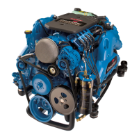
Figure 3-5 - Pressure Regulator Assembly (Typical)
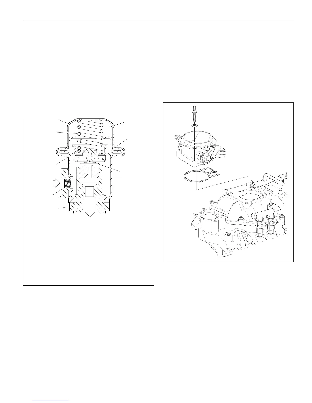
Figure 3-6 - Throttle Body Assembly
1 COVER
2 VACUUM CHAMBER
(VACUUM SOURCE TUBE NOT SHOWN)
3 O - RING SEAL
4 FUEL PRESSURE REGULATOR VALVE
5 BASE ASSEMBLY
6 FILTER SCREEN (IF EQUIPPED)
7 DIAPHRAGM
8 SPRING
NA 0493-SY
1
8
7
6
5
2
3
4
4-11-96
Throttle Body Assembly
The throttle body assembly is attached to the intake
manifold air plenum, and is used to control air fl ow into the
engine, thereby controlling engine output (Figure 3-6). The
throttle plates within the throttle body are opened by the
driver through the throttle controls. During engine idle, the
throttle plates are closed, and air fl ow control is handled by
the Idle Air Control (IAC) valve, described below.
The throttle body also provides the location for mounting
the TP sensor and for sensing changes in engine vacuum
due to throttle plates position.
Pressure Regulator Assembly
The pressure regulator is a diaphragm-operated relief
valve with fuel pump pressure on one side, and regulator
spring pressure and intake manifold vacuum on the other
side (Figure 3-5). The regulator’s function is to maintain
a constant pressure differential across the injectors at all
times. The pressure regulator compensates for engine load
by increasing fuel pressure as engine vacuum drops.
With the ignition “ON,” engine “OFF” (zero vacuum),
fuel pressure at the pressure test connection should be
284-325 kPa (41-47 psi). If the pressure is too low, poor
performance or a “no-start” may result. If pressure is too
high, excessive odor may result.
 Loading...