POCLAIN HYDRAULICS
800078181E DOC-REPAIR-MK05-MKE18-FR-EN 7
INTERVENTION
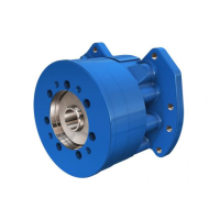
Remplacement du moteur
Dépose
• Éliminer la pression dans le circuit d'alimentation.
• Débrancher la tuyauterie de drainage au niveau
du réservoir afin d'éviter le siphonnage de celui-ci.
• Débrancher et boucher les tuyauteries ou
flexibles raccordés sur le moteur.
• Débrancher le connecteur du capteur tachy
• Démonter les vis de fixation, puis déposer le
moteur.
• Vidanger le carter.
Repose
• Contrôler l'état du plan de fixation.
• Mettre en place le moteur
• Monter et serrer les vis de fixation. (voir tableau)
• Rebrancher le connecteur du capteur tachy (option)
• Déboucher et rebrancher les tuyauteries ou
flexibles sur le moteur.
• Rebrancher la tuyauterie de drainage au niveau du
réservoir.
• Procéder au remplissage du carter.
Veuillez vous reporter aux documentations suivantes :
• INSTALLATION MK F/GB (ref. 677777846M
)
• INSTALL GENERIQUE F (ref. 801478127K)
MAINTENANCE
Replacing of the motor
Removal
• Release the pressure in the supply lines.
• Disconnect the drain lines at the tank level to
avoid its siphoning.
• Disconnect and plug the pipes or hoses which
are connected to the motor.
• Disconnect the speed sensor
• Disconnect the mounting screws, and remove
the motor.
• Drain the casing.
Reinstallation
• Check the condition of the motor’s mounting
surface.
• Position the motor.
• Install and tighten the mounting screws.(see table)
• Reconnect the speed sensor (optional).
• Remove the plugs and reconnect the pipes or
hoses to the motor.
• Reconnect the drain line at the tank level.
• Fill the casing.
Please refer to the following documentation brochures :
• INSTALLATION MK F/GB (ref. 677777846M
)
• INSTALL GENERIQUE GB (ref. 801478197L)
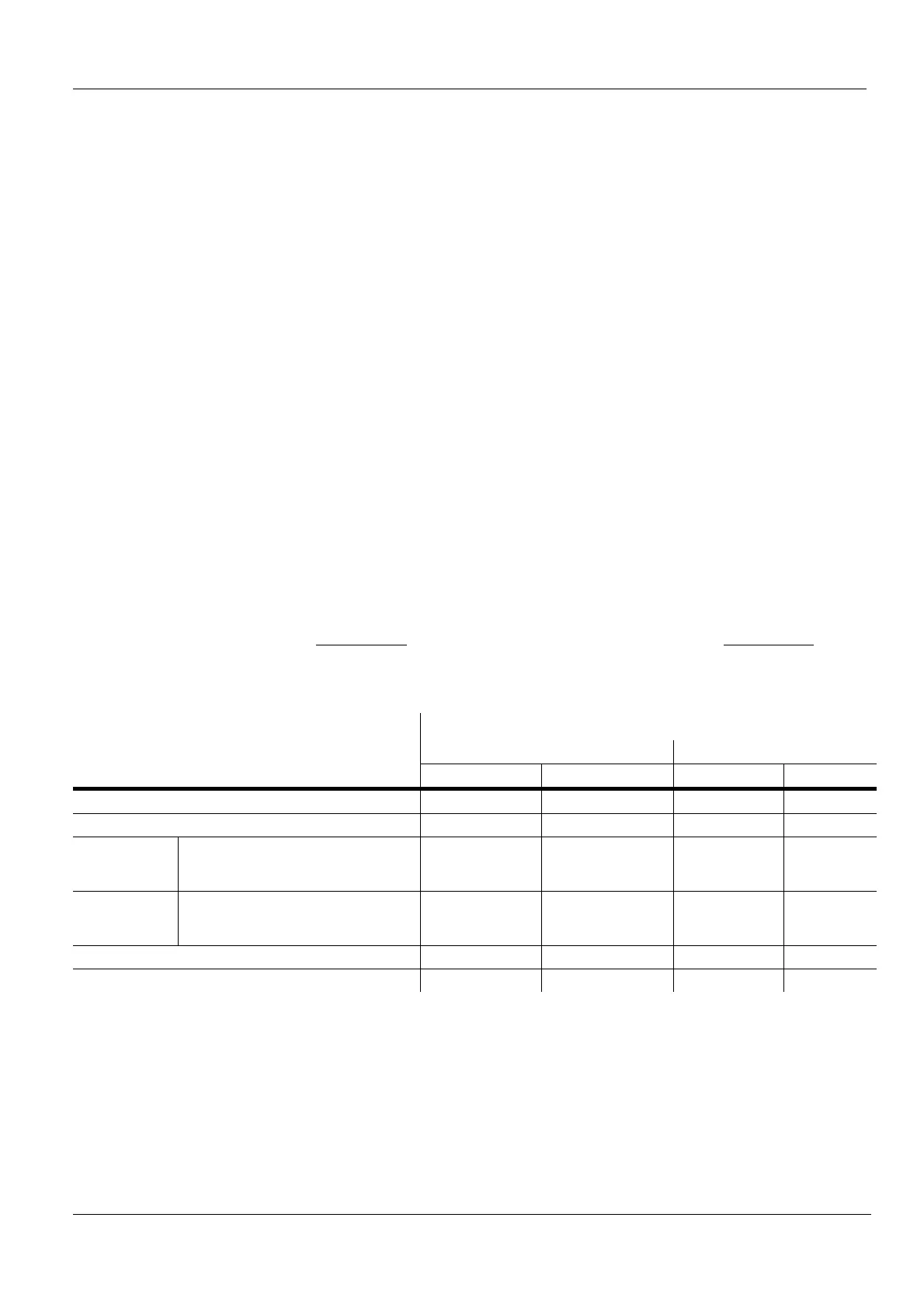
Couple de serrage
(1)
Tightening torque
(2)
± 10%
cl 10.9 cl 12.9
Moteurs Motors
N.m
lbf.ft
N.m
lbf.ft
MK05 (7 x M16)
300
222
350
260
MK08 (9 x M16)
300
222
350
260
MK09 (M12)
Le nombre et la taille des vis
dépendent de la plaque client
(M12 ou M16)
120
88.5
230
170
MK09 (M16)
The number and the size of the
screws depend on the plate
customer (M12 or M16)
300
222
350
260
MK11 (8 xM16)
300
222
350
260
MK18 MKE18 (8 xM20)
580
428
690
509
(1)
Les couples de serrage sont donnés à titre indicatif
(2)
Tightening torques are given for information only.