3.38
9929422 R02 - 2017-2019 ACE 900 Service Manual
© Copyright Polaris Industries Inc.
16.Install the three fasteners
u
retaining the harness by
the transmission switch and two fasteners
i
retaining the taillight harness wires to the frame.
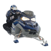
17.Install the three harness clamps
o
on the intake
manifold.
18.Connect the wiring leads and spark plug caps.
19.Install the four fasteners
a
securing the airbox
support to the frame. Ensure the heat shield
s
is
properly secured to the airbox support
20. Install the two bolts mounting the air box to the frame
bracket and tighten the clamp on the air box duct .
Also tighten the PVT intake clamp . Install the four
screws mounting the engine and PVT intake vents.
Torque fasteners to specification.
TORQUE
Duct Clamp:
35 in-lbs (4 Nm)
Air Box Mounting Bolts:
8 ft-lbs (11 Nm)
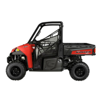
21.Install the coolant hoses onto the engine.
22.Install the six exhaust head pipe fasteners
j
and the
two springs retaining the pipe to the muffler
k
.
Torque screws to specification.
TORQUE
Exhaust Head Pipe Screws:
18 ft-lb (24 Nm)
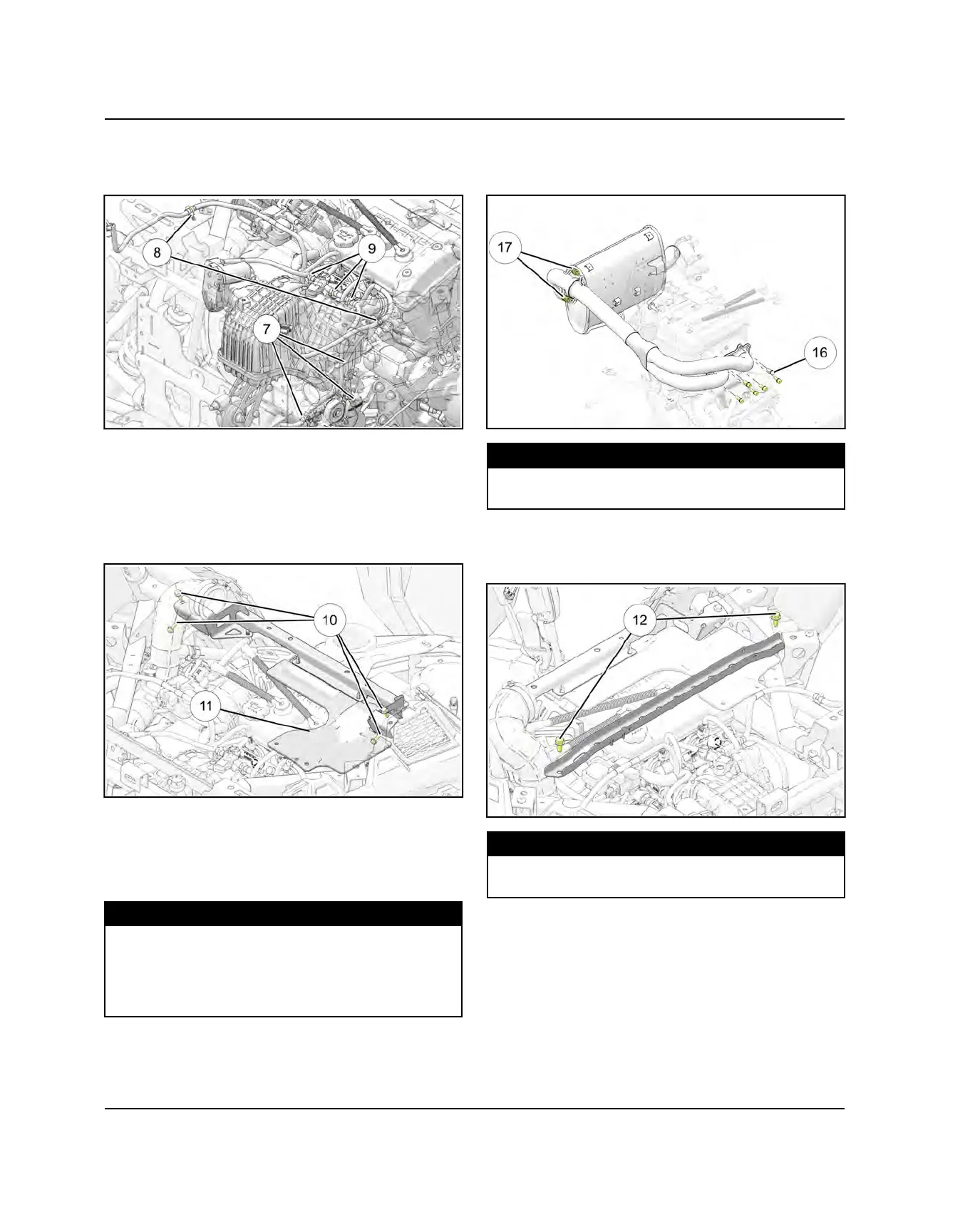
23.Install the rear frame brace. Torque screws
d
to
specification. Route the transmission vent hose
across the top of the brace.
TORQUE
Rear Frame Brace Screws:
14 ft-lbs (19 Nm)
ENGINE / COOLING SYSTEM

 Loading...