2
9929422 R02 - 2017-2019 ACE 900 Service Manual
© Copyright Polaris Industries Inc.
2.23
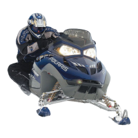
6. Remove the (4) T40 bolts
q
and rubber isolators
w
retaining the valve cover. Note the location and use of
the grounding washer
r
for assembly.
NOTE
Replace rubber isolators
w
upon assembly.
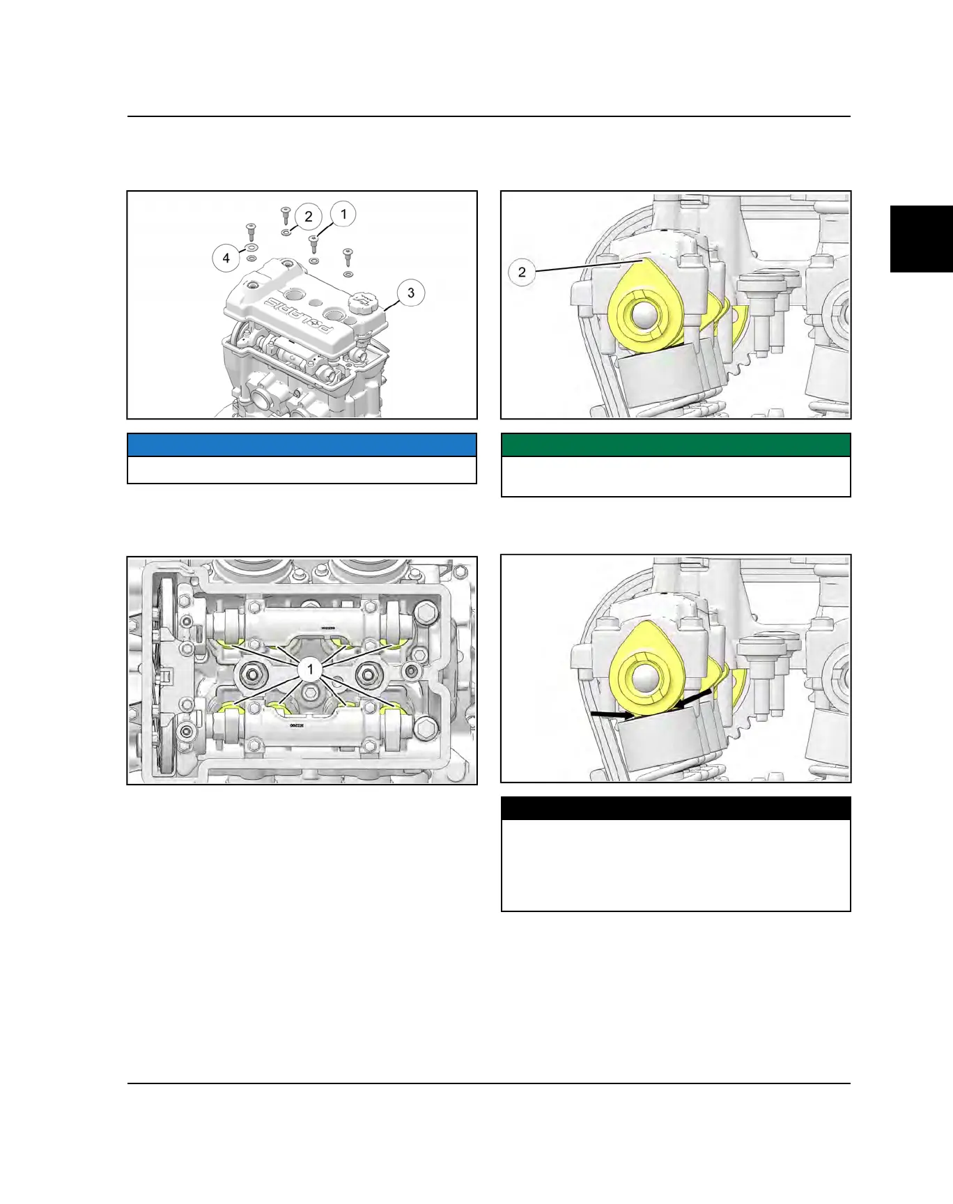
7. The engine will need to be rotated four times to
inspect all eight valve clearances
q
. Two valves can
be measured at each camshaft lobe position.
8. Rotate the drive clutch counter-clock wise until the
cam lobes
w
above the valves you are inspecting are
facing up.
IMPORTANT
Do not rotate the engine backwards. The timing chain
may jump teeth and lead to poor performance.
9. Measure the valve clearance of each valve using a
feeler gauge.
MEASUREMENT
Intake Valve Clearance:
0.006 ± 0.002" (0.15 ± 0.05 mm)
Exhaust Valve Clearance:
0.008 ± 0.002" (0.20 ± 0.05 mm)
10.Record the results of each measurement for future
reference.
11. If the valve clearances are out of specification,
proceed to Valve Clearance Adjustment page 3.89.
MAINTENANCE
 Loading...