-
-
-
-
-
-
-
r--.,
STARr
BUTTON
LeVeR
lENGAGEDJ
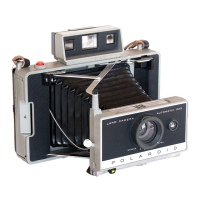
FIG.
2.11
INTERNAL CONFIGURATION
OF
THE MECHANICAL TIMER
-
which indicates
that
the
timer is in operation.
Thls
is
accomplished
by
the
revolution
of
the
large~tooth
gear
as
it brushes past
the
cutout
on
the wheel,
It
strikes the
whed
producing a
-
''wltirringn sound,
The
second purpose
of
the
gears is
to
proVide a means by w hleb
the
timer
-
can
be
stopped.
Note
that
the
start
button
is
connected
to
a Ie\'er. Moving
the
button
to
the
right (as viewed from outside
the
camera) causes
the lever
to
engage
the
large-toothed gear. This
-
stops
the
gears which. in
tum,
stops
the
main~
spring,
-
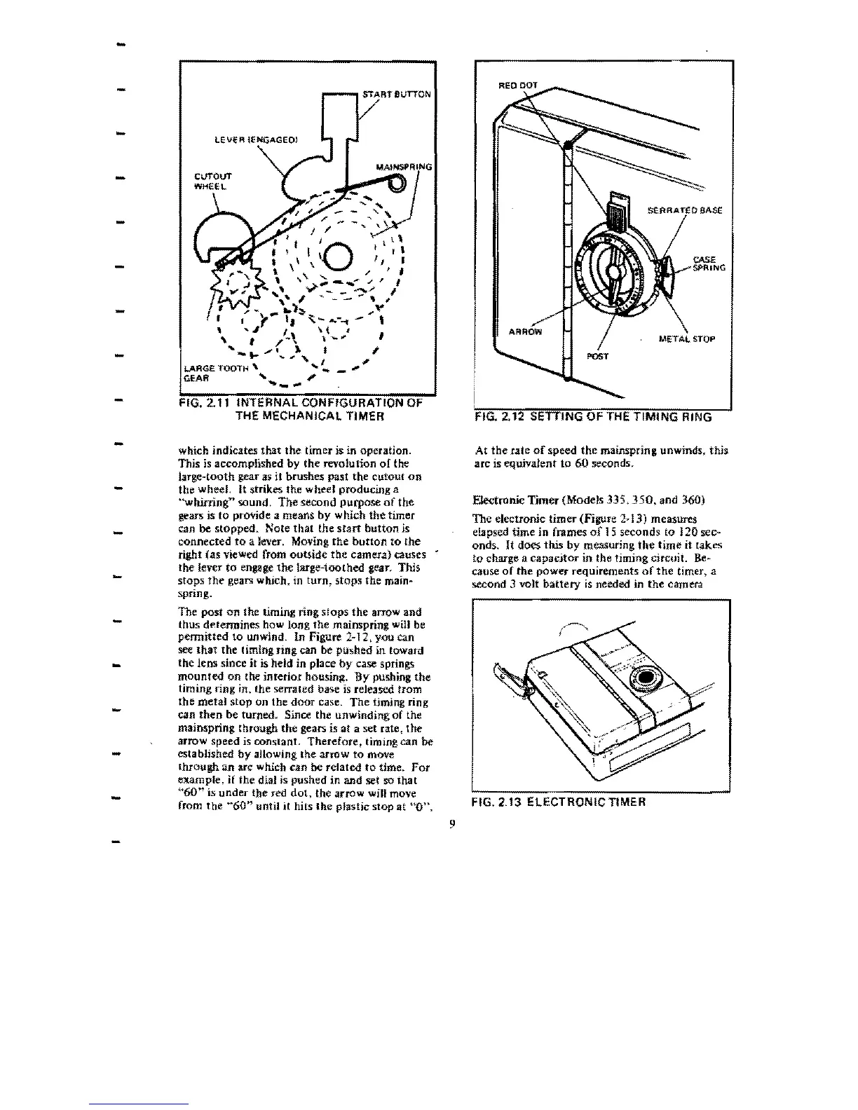
The
post
on
the timing ring Slops
the
arrow and
thus determines how long
the
mainspring will be
permitted
to unwind. In Figure 2-12, you can
see
that
the
liming nng can be pushed in toward
-
the
lens since
it
is held in place
by
case springs
mounted
on
the interior housing.
By
pushing
the
timing ring in.
the
serrated base
is
released from
-
the
metal
stop on
the
door
case.
The
timing
ring
can
then
be turned. Since the unwinding
of
the
mainspring through
the
gears is
at
a
set
rate,
the
arrow speed is conslanL
Therefore,
timing can
be
established
by
allOWing
the
arrow
to
move
-
through
an
arc which can be related
to
time.
For
example,
if
the dial is pushed
in
and set so Ihat
-
"60"
is
under
the
red
dot,
the
arrow will move
from
the
"60"
until
it
hits
the
plastic stop
ilt
"0",
9
FIG. 2.12 SETTING OF THE TIMING RING
At
the
rate
of
speed
the
mainspring. unwinds. this.
arc is equiVatent
to
60 seconds.
Electronic
Tjmer
(Models 335,
350.
and 360)
The electronic
timer
(Figure
2~
13) measures
elapsed time
in
frames
of
15
seconds to J
20
sec~
onds.
It
does
this
by
measuring
the
time
it
takes
to charge a
capacitor
in the timing circuiL
Be~
cause
of
the
power
requirements
of
the
timer, a
second 3 volt
battery
is
needed in
the
camera
FIG. 2.13 ELECTRONIC TIMER
 Loading...