Home
Polaroid
Digital Camera
100 Series
Polaroid 100 Series User Manual
4
of 1
of 1 rating
81 pages
Give review
Manual
Specs
To Next Page
To Next Page
To Previous Page
To Previous Page
Loading...
bid
t)J!
Ih~'
front
roll.
imliLatin!,!.
the
modillcation
ha:.
lWl."1l
Jon~'.
I.
Rcpi;.hv
!
he
l>pr~~ld
roll
sluing
t
Figure
5-7):
U"ld
I
h
...
·
rddiu:>
end
of
tilt.'
spring
and
insl'rt
tlw
:.pring in
till'
fr:Jme
roller
support
so
thnt
Ih~'
Inw~'r
l'ml
of
thl'
spring
seats
on
the
frnnl
mJl
:mpport
tab.
Apply.oJ
downward
rr~'s~lIr~'
on
the
upper
end
of
the
spring
and
forc~'
th~'
spring
under
the
frame
roller
support
tab,
""!
Replacl"
the
front
{shouldered)
roU;
Place
lill"
roll
bushinp
on
the
roU
and
insert
one
end
of
the
roU
in
either
snppon.
Spread
the
ot
her
support
far
enough
to
insert
the
roU.
Check
the
end-t<>-end
play
of
the
roll
in
the
supports.
This
side
mcwement
must
not
ex.-
ceed
.o:!o
inch.
If
it
does,
remove
the
roU
and
tot'
in
the
front
roll
suppons.
Re--install
the
ron
and
recheck.
3.
Replace
the
rear
roU;
Place
the
ron
on
top
of
the
fronl
ron
and
line
up
the
bushings
with
the
openings
in
the
support.
Press
down
finn~
I)'
unti1
one
end
of
the
ron
snaps
into
posi-
tion
in
the
supporL
Press
down
at
the
other
end
until
the
roll
is
engaged
in
the
support.
SHUTI'ER
HOl:SING
REPLACEMENT
Removal
[.
R<'m(lh"
I
h
...
(ront
shutter
housing
and
the
IXb~'
t'llol.:k
aml
de.:tronic
module
as
follows:
J.
L.
\(,:nl!
tlw
i'>.:llqW~
to
detent
lock-in.
h
Knllm\:
I
Ill'
.,IILlth'T
housing
screws
(indud~
Jl)j.'
t!)~·
lHlllSil1~
'~T"'\\
.11
fhe
lop
of
tht"
L·
..
ble
,,-'1,,1-'"
,:o,,,;p
io~·.IIVd
on
the
bellows-side
of
1!l\.'
r~',1f
"IHlner
htm:'lIlj:!
USing
scrl'wdrivcr
.:::
I
j
{1-tO.
iOn
':.JlUcr
..
:.
where
aprlicabk,
:\.'h'.I"~·
Ih~'
front
shutt('r
housing
from
the
1\'1'
~'l~-li
pbk_
If
t[k'
el~h
plate
is
d:lmaged
"1'1:",
1t"'1
It-.
:JJ!h·SJWIlC~.
discard
iLl
,'.
\\h~'r;.:
apptk';lhk.
f~'mo\'e
lhe
hasc
block
:lIld
('k,:1foni
..
'
Illutluk
mounting
screws
holdmg
lh~
.,liull",r
10
tlw
fronl
shutt..:r
housing.
(On
.,Olll\.'
":;UTIcras..
the
:.hutter
simply
rests
on
I'I,!:-"!I~'
p'hb.!
d.
On
shutler-.
with
copper"'COlorcd
mylar
J)rin(ed
eircuils:
~nte
the
posltions
of
lilt:
btal.:t.:
anti
WIllI\:
b<Jth:ry
WI~
kads.
Using
an
l·np
r
"sol<kr
gobbler"
'or
l'quivai1:nt
J.
carefully
IIn~oILl
..
·r
the
two
h.:;Ilis.
Cui
off
and
S<lW
IhL'
rubher
strain~rdief
collar
blit
thl.!
coUar
and
pee}
if
off
the
alhll..'j
;)nd
df"JW
the
battery
win,'
through
th.:
opening
in
the
rear
shutter
hOllsing,
On
shutters
witb
cleat
teflon
printed
circuits
tolder
Model
100
cameras):
DO
NOT
UNSOLDER
THE
BATI'ERY
LEADS
FROM
THE
CIRCUIT!
Open
the
baUery
compartment
and
unsolder
the
black
battery
lead
from
the
shutter
inter-
lock.
Snip
the
white
Jead
about
an
inch
away
from
the
battery
tenninaJ.
Remove
and
retain
the
metal
banding
dip
and
draw
the
battery
wire
through
the
bellows
tabs
and
the
opening
in
the
rear
shuUer
housing.
On
other
shutters:
Unsolder
the
battery
leads
diItctly
from
their
contacts
On
the
electronic
module,
cut
the
collar
(slit
the
coJJar
and
peel
it
off
the
cable)
and
draw
the
'wire
through
the
opening
in
the
shutter
hQusing.
2.
Loosen
the
cable
Itlease
cover
retaining
screws
and
free
the
cable
release
from
the
Itar
shutter
housing.
(Refer
to
Figures
5-21
and
5-22
for
the
following
steps.)
3.
To
remove
the
inner
frame
(top)
from
the
shutter
housing.
remove
the
detent
from
the
detent
stud
using
smooth
edged
plier--..
(The
detent
is
press--fitted
on
the
~ud,)
Then
un~
screw
the
detent
stud
from
the
shutter
shaft,
thus
releasing
the
inner
frame
(top).
4.
To
remove
the
inner
frame
{bottom
J
from
tbe
shurter
housing.
remove
the
shutler
shaft
screw
and
the
two
washers
(if
present)
from
the
shutter
mount.
Next
remove
the
shutter
shaft
and
sleeve
(if
present)
from
the
housing.
5.
Release
the
U~frame
from
the
shutter
hous
w
lng
by
sliding
the
bushing
out
of
the
key·
hole.
Release
the
spring
from
the
shutter
mQunt.
6.
Collapse
rhe
beHows
and
remove
the
rc;.;r
shutler
housing
from
the
bellows
as
follows
j
ret:Jin
the
light
seal).
Models
100.240_
250_
350
&
360;
Remove
the
four
bellows
screws.
All
Other
Models:
Remove
the
four
bellows
fasteners
using
tool
#11006
(Figure
5-8}.
,Some
newer
model
48
50
Table of Contents
Table of Contents
2
Section I . Introduction
8
Section II . Princip'es of Operation
9
The Spread System
10
The Focusing System
11
Lenses
11
Rangefioderslviewfinders
12
Image Sizer
12
Potaroid Rangefinder/Viewfinder
13
Zeiss Ikon Rangefinder/Viewfinder
14
Timers
15
Mechanical T IM.r
15
Electronic Timer
16
Flashgun
17
Section III " Camera Checkout
20
Checking Shutter Battery Voltage
22
Checking the Shutter Interlock
22
Checking the Shutter Release Burton
22
Measuring Timer Acturacy
22
Measuring Timer Battery Voltage and Current Drain
23
Checking the Lens and Rangefinder/Viewfinder (Collimation)
23
Rangefinder/Viewfinder Parallax Check
25
Image Sfzer Parallax Check
26
Bellows Light Leak Test
26
Flashgun Testing
26
Section IV - Troubleshooting Charts
28
Problems Evidenced in Pictures
28
Electronic Timers
32
Mechanical Timers
34
Spread System
36
Rangefinder/Viewfinders
38
Miscellaneous
40
Model 268 Flashgun
42
Section V . Repairs and Adjustments
44
Conversion of Pack Cameras with Serial Numbers Starting with "AA
44
Serial Number Transfer
45
Rear Door {Back Cover) Replacement
45
Exit Door Replacement
46
Slide Block Replacement
46
Spread Roll Spring Replacement
47
Shutter Housing Replacement
49
Bellows. Replacement
51
Front Lens Reptacement
53
Rear Lens Replacement
55
Lens Bezel Replacement
57
Flash Filter and Cell Wedge Replacement
57
Photoci!Ti Lens Replacement
58
Focus Bar Replacement
58
Inner Frame (Top) Replacement
59
Inner Frame (Bottom) Replacement
60
U· Frame Assembly R Eptacement
60
Shutter Release Cabje Replacement and Adjustment of Retease Button
61
Battery I Nterlock Replacement
62
ADJUSTING the Battery INTERLOCK SWITCH
63
Battery C_E and Left Hand Guard Replacement
63
Replacing the Electronic Timer
67
Electronic Timer Switch Continuity Check &: Adjustment
69
Replacement of Image Sizers
70
Replacement of Non-Folding Rangefinder/Viewfinders
71
Replacement of Folding Rangefinderniewfinders
71
Replacement of Polaroid RFNF Optics Assembty & VF Window
71
Replacement of Folding RFIVF Magnet
72
Replacement of Folding R F IV F Pivot Pads
73
Rangefinder/Viewfinder and Image Sizer Adjustments
73
Lens Col1Imation
78
Replacement of Cantilev-Er Assemblies and Housings in Polaroid RF/V F
79
Conversion of 4,5NOC Flashguns and Replacement of Old Battery Clip
81
4
Based on 1 rating
Ask a question
Give review
Questions and Answers:
Need help?
Do you have a question about the Polaroid 100 Series and is the answer not in the manual?
Ask a question
Polaroid 100 Series Specifications
General
Image Sensor
CCD
Optical Zoom
3x
Digital Zoom
4x
Shutter Speed
1/2 - 1/2000 sec
Video Resolution
640 x 480
Storage Media
SD card
Battery Type
2 x AA
Related product manuals
A500 - 5.1MP Digital Camera
44 pages
Polaroid Automatic 100
52 pages
Polaroid 620
37 pages
Polaroid Snap
12 pages
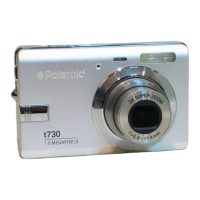
Polaroid t730
62 pages
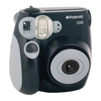
Polaroid PIC 300
2 pages
Polaroid DIGITAL 320
19 pages
Polaroid 600 Close-up
4 pages
Polaroid One600 Ultra
6 pages
Polaroid OneStep SX-70
21 pages
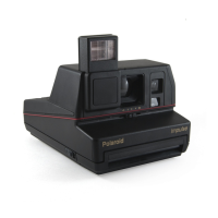
Polaroid impulse series
11 pages
Polaroid Digital Camera
67 pages