Home
Polaroid
Digital Camera
100 Series
Polaroid 100 Series User Manual
4
of 1
of 1 rating
81 pages
Give review
Manual
Specs
To Previous Page
To Previous Page
Loading...
would
~tlrtl's(loml
10
till'
infinity
SI.,·tting)
dis.:n~
gol!,"
tb\'
ior:aoll
liprin~
and
b~'nd
it
buck
SO
il
wHl
\'\:crl
more
TCllliiOf}
on
the
light
pipe.
Pl:li:e
the
sprint!
baC'k
on
the
tab
and
move
thl.'
cam
baek
.1I1rJ
forth
a
few
times
to
see
if
the
mask
is
moving
properly,
If
it
is
stili
sticking.
continue
below.
If
it
lS
OK
and
tht>
rest
of
the
image
sizer
is
OK.
Llssl.'mbh:
tb
...
rear
assembly
to
the
front
housing
tstl'PS
13.
l4.
and
IS).
4,
Rl.'lnovl.'
the
cam
Llnd
disengage
the
torsion
sprillg
from
the
tab
on
the
light
pipe.
5.
Carefully
pry
up
[he
mirror
retaining
spring
and
baftle
plate
from
the
two
posts.
6.
Replace
any
of
the
inner
components
which
are
found
to
be
defective.
Before
removing
either
the
fixed
mask
or
the
negative
lens.
note
how
the
adjusting
spring
is
instaUed.
Also
note
the
position
of
the
fIxed
mask.
The
slant
of
the
adjusting
spring
slot
on
the
mask
runs
upward
from
left
to
right.
7.
Following
Plate
B
of
Section
VI,
reassemble
the
image
sizer.
Place
the
fixed
mask.
on
the
negative
Jens
and
install
the
adjusting
spring.
(The
shorter
side
of
the
sprin,g
goes
over
the
mask
while
the
longer
side
goes
over
the
outside
surface
of
the
negative
lens.
The
9Q.degree
bend
in
the
longer
side
rides
On
the
lOp
of
the
lens.)
S,
Position
the
moving
mask
onto
the
light
pipe
ilnd
pJace
them
over
the
fixed
mask
Be
sure
Ihe
1;lb
on
the
light
pipe
fits
into
the
slot
on
rh\.'
negative
lens.
9,
{nsw!l
the
negative
tens
on
the
front
housing.
10.
J
nsraU
the
torsion
spring
and
spacer
on
the
Iowa
post
of
the
negative
lens.
The
short
\.'IlU
of
(he
spring
must
be
trapped
between
,h\.,
fli.'gaUve
lens
post
:Jnd
the
housing
post.
II.
For,>.:
the
b:.lm~
pijte
and
mirror
retaining
..
prllil;
hild.
over
the
two
posts..
; 2
Hook
thl.'
torsion
spring
onto
the
light
plpe
{,lh
Jild
position
Ihe
cam
under
the
tab,
MOVt'
the
c:.Im
all
the
way
to
the
left
(or
to
fhl'
mfmity
setting).
l.~,
C.lrdully
phH:e
the
front
housing
assembly
UHO
Ih~'
r\.'ilr
assembly
and
seCUre
the
two
\\'Jlh
Ihe
assembly
screws.
I..J-.
P~hition
Ih~
t'am
into
the
slot
on
the
focus
bar
l
aT
til\'
infinity
setting)
and
secure
the
Imag~'
sizer
10
the
camera
body
with
the
Phillipyhead
sc£cw.
15.
Perform
the
lmJge
siLer
ran'se
and
paranax
ad_ttlSlJm~nh
noted
in
Seclion
HI.
74
CONVERSION
OF
4.S·VDC
FLASHGUNS
AND
REPLACEMENT
OF
OLD
BATTERY
CLIPS
Removal
I.
Remove
the
slotted
saews
holding
the
mounting
foot
to
the
base
assembly
and
re-
move
the
mounting
foot.
'"
Remove
and
discard
the
4,5~vdc
battery.
3.
Remove
the
PhiIJips
nat~head
screws
holding
the
battery
mounting
plate
and
insulator.
Discard
the
mounting
plate.
4.
Jnspect
the
battery
dip
under
(he
insulator.
If
it
is
a
stainless
steel
or
phosphor
bronze
battery
cliP.
remove
and
discard
it.
Replacement
J.
Position
a
new
gold-plated
battery
clip
Jill
55326
intO
the
base
....
mbly.
2.
Install
the
insulator
and
a
new
battery
mount-
ing
plate
#155332
and
secure
them
with
the
two
PhJnips
Oat..tlead
screws.
3.
To
compensate
for
the
size
difference
be~
tween
the
old
4.5-vdc
battery
and
the
new
L5-vdc
battery,
it
is
necessary
to
add
a
fiUer
pad
to
the
inside
of
the
mounting
fool.
Apply
a
smaJJ
amount
of
Elmer's
glue
to
filler
pad
fl168177
and
position
the
pad
on
the
inside
surface
of
the
mounting
foot
as
shown
in
Figure
5·59.
(Some
of
these
filler
pads
are
seJf.-adhesiveJ
CENTER
HERE
fILLER
+
PAO
MOUNTING
FOOT
o
o
FIG.
5.59
CENTERING
HIE
FILLER
PAD
4.
(nstan
a
new
L5~vdc
battery
in
the
flashgun.
S.
Replace
the
mounting
foot
on
the
Oashgun
and
seCUre
it
wjth
the
two
slotted
screws,
80
Table of Contents
Table of Contents
2
Section I . Introduction
8
Section II . Princip'es of Operation
9
The Spread System
10
The Focusing System
11
Lenses
11
Rangefioderslviewfinders
12
Image Sizer
12
Potaroid Rangefinder/Viewfinder
13
Zeiss Ikon Rangefinder/Viewfinder
14
Timers
15
Mechanical T IM.r
15
Electronic Timer
16
Flashgun
17
Section III " Camera Checkout
20
Checking Shutter Battery Voltage
22
Checking the Shutter Interlock
22
Checking the Shutter Release Burton
22
Measuring Timer Acturacy
22
Measuring Timer Battery Voltage and Current Drain
23
Checking the Lens and Rangefinder/Viewfinder (Collimation)
23
Rangefinder/Viewfinder Parallax Check
25
Image Sfzer Parallax Check
26
Bellows Light Leak Test
26
Flashgun Testing
26
Section IV - Troubleshooting Charts
28
Problems Evidenced in Pictures
28
Electronic Timers
32
Mechanical Timers
34
Spread System
36
Rangefinder/Viewfinders
38
Miscellaneous
40
Model 268 Flashgun
42
Section V . Repairs and Adjustments
44
Conversion of Pack Cameras with Serial Numbers Starting with "AA
44
Serial Number Transfer
45
Rear Door {Back Cover) Replacement
45
Exit Door Replacement
46
Slide Block Replacement
46
Spread Roll Spring Replacement
47
Shutter Housing Replacement
49
Bellows. Replacement
51
Front Lens Reptacement
53
Rear Lens Replacement
55
Lens Bezel Replacement
57
Flash Filter and Cell Wedge Replacement
57
Photoci!Ti Lens Replacement
58
Focus Bar Replacement
58
Inner Frame (Top) Replacement
59
Inner Frame (Bottom) Replacement
60
U· Frame Assembly R Eptacement
60
Shutter Release Cabje Replacement and Adjustment of Retease Button
61
Battery I Nterlock Replacement
62
ADJUSTING the Battery INTERLOCK SWITCH
63
Battery C_E and Left Hand Guard Replacement
63
Replacing the Electronic Timer
67
Electronic Timer Switch Continuity Check &: Adjustment
69
Replacement of Image Sizers
70
Replacement of Non-Folding Rangefinder/Viewfinders
71
Replacement of Folding Rangefinderniewfinders
71
Replacement of Polaroid RFNF Optics Assembty & VF Window
71
Replacement of Folding RFIVF Magnet
72
Replacement of Folding R F IV F Pivot Pads
73
Rangefinder/Viewfinder and Image Sizer Adjustments
73
Lens Col1Imation
78
Replacement of Cantilev-Er Assemblies and Housings in Polaroid RF/V F
79
Conversion of 4,5NOC Flashguns and Replacement of Old Battery Clip
81
4
Based on 1 rating
Ask a question
Give review
Questions and Answers:
Need help?
Do you have a question about the Polaroid 100 Series and is the answer not in the manual?
Ask a question
Polaroid 100 Series Specifications
General
Image Sensor
CCD
Optical Zoom
3x
Digital Zoom
4x
Shutter Speed
1/2 - 1/2000 sec
Video Resolution
640 x 480
Storage Media
SD card
Battery Type
2 x AA
Related product manuals
A500 - 5.1MP Digital Camera
44 pages
Polaroid Automatic 100
52 pages
Polaroid 620
37 pages
Polaroid Snap
12 pages
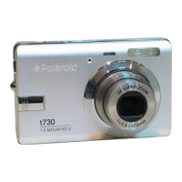
Polaroid t730
62 pages
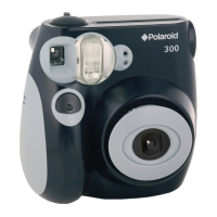
Polaroid PIC 300
2 pages
Polaroid DIGITAL 320
19 pages
Polaroid 600 Close-up
4 pages
Polaroid One600 Ultra
6 pages
Polaroid OneStep SX-70
21 pages
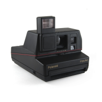
Polaroid impulse series
11 pages
Polaroid Digital Camera
67 pages