Home
Polaroid
Digital Camera
100 Series
Polaroid 100 Series User Manual
4
of 1
of 1 rating
81 pages
Give review
Manual
Specs
To Next Page
To Next Page
To Previous Page
To Previous Page
Loading...
SECTION
II
-
PRINCIPLES
OF
OPERATION
THE
FILM
PACK
A
d~:o.t:ripfion
of
the
Polaroid
Land
pack
I..'ilmera
~hould
beltin
with
an
explanation
of
the
operation
of
tht>
film
p:u;k
itself.
The
following
description
1s
Olpplk:able
to
both
the
black
and
white
(Type
107)
lind
rhe
color
(Type
t
08)
film
pack.
Figure
2~1
is
a
cross-sectional
representation
of
a
film
pack
looded
in
the
camera.
The
black
safety
cover
which
normally
surrounds
the
negative
and
positive
material
has
been
removed.
positioning
the
first
white
tab
in
the
number
4
slot
of
the
rear
door
assembly.
The
ejghl
negatives.
each
with
its
own
pod
of
developing
jelly.
are
held
in
posifion
by
the
spring~loaded
pressure
plate.
On
the
other
side
of
the
pressure
plate
is
the
stack
of
eight
positives.
Both
the
negative
and
its
corre-
sponding
positive
is
joined
by
a
paper
leader
to.
it
yellow
tab,
In
turn,
the
yeUo'>;V
tab
is
cennected
to
the
white
tab.
Pulling
the
white
tab
out
ef
the
camera
(after
the
negative
has
been
expos,ed)
accomplishes
two
thjn~
as
shown
in
Figure
2~2.
(To.
simplify
matters,
the
illustration
shows
only
one
negative
and
one
positive.)
First,
it
feeds
the
yellow
tab
be1ween
the
rollers.
and
out
the
door.
Second.
it
pulls
the
exposed
negative
around
the
pressure
plate
50
it
faces.
the
positive
sheer.
It
should
be
~lTesscrl
thal
pulling
the
white
tab
out
of
the
POD
TAB
FIG.
2.1
PACK
LOADED
IN
CAMERA
camera
does
not
start
picture
development.
It
simply
places
aU
of
the
picture
assembJy
pans
in
the
proper
position
for
the
next
step.
To
develop
the
picture,
the
yellow
tab
is
pulled
out
ef
the
camera
as
shown
in
Figure
2-3.
This
action
bursts
the
pod
on
tbe
negative.
As
the
negative
and
positive
are
drawn
through
the
rollers.,
an
even
coating
of
deveIopingjelly
is
spread
between
the
two.
sheets-
The
picture
then
develeps
outside
the
camera.
-.-
--
-
TAB
YEllOW
FIG.
2.2
WHITE
TAB
BEING
PULLED
JE('lY
-
..
ROtJ
...
EAS
FIG.
2.3
YELLOW
TAB
BEING
PULLED
8
10
Table of Contents
Table of Contents
2
Section I . Introduction
8
Section II . Princip'es of Operation
9
The Spread System
10
The Focusing System
11
Lenses
11
Rangefioderslviewfinders
12
Image Sizer
12
Potaroid Rangefinder/Viewfinder
13
Zeiss Ikon Rangefinder/Viewfinder
14
Timers
15
Mechanical T IM.r
15
Electronic Timer
16
Flashgun
17
Section III " Camera Checkout
20
Checking Shutter Battery Voltage
22
Checking the Shutter Interlock
22
Checking the Shutter Release Burton
22
Measuring Timer Acturacy
22
Measuring Timer Battery Voltage and Current Drain
23
Checking the Lens and Rangefinder/Viewfinder (Collimation)
23
Rangefinder/Viewfinder Parallax Check
25
Image Sfzer Parallax Check
26
Bellows Light Leak Test
26
Flashgun Testing
26
Section IV - Troubleshooting Charts
28
Problems Evidenced in Pictures
28
Electronic Timers
32
Mechanical Timers
34
Spread System
36
Rangefinder/Viewfinders
38
Miscellaneous
40
Model 268 Flashgun
42
Section V . Repairs and Adjustments
44
Conversion of Pack Cameras with Serial Numbers Starting with "AA
44
Serial Number Transfer
45
Rear Door {Back Cover) Replacement
45
Exit Door Replacement
46
Slide Block Replacement
46
Spread Roll Spring Replacement
47
Shutter Housing Replacement
49
Bellows. Replacement
51
Front Lens Reptacement
53
Rear Lens Replacement
55
Lens Bezel Replacement
57
Flash Filter and Cell Wedge Replacement
57
Photoci!Ti Lens Replacement
58
Focus Bar Replacement
58
Inner Frame (Top) Replacement
59
Inner Frame (Bottom) Replacement
60
U· Frame Assembly R Eptacement
60
Shutter Release Cabje Replacement and Adjustment of Retease Button
61
Battery I Nterlock Replacement
62
ADJUSTING the Battery INTERLOCK SWITCH
63
Battery C_E and Left Hand Guard Replacement
63
Replacing the Electronic Timer
67
Electronic Timer Switch Continuity Check &: Adjustment
69
Replacement of Image Sizers
70
Replacement of Non-Folding Rangefinder/Viewfinders
71
Replacement of Folding Rangefinderniewfinders
71
Replacement of Polaroid RFNF Optics Assembty & VF Window
71
Replacement of Folding RFIVF Magnet
72
Replacement of Folding R F IV F Pivot Pads
73
Rangefinder/Viewfinder and Image Sizer Adjustments
73
Lens Col1Imation
78
Replacement of Cantilev-Er Assemblies and Housings in Polaroid RF/V F
79
Conversion of 4,5NOC Flashguns and Replacement of Old Battery Clip
81
4
Based on 1 rating
Ask a question
Give review
Questions and Answers:
Need help?
Do you have a question about the Polaroid 100 Series and is the answer not in the manual?
Ask a question
Polaroid 100 Series Specifications
General
Image Sensor
CCD
Optical Zoom
3x
Digital Zoom
4x
Shutter Speed
1/2 - 1/2000 sec
Video Resolution
640 x 480
Storage Media
SD card
Battery Type
2 x AA
Related product manuals
A500 - 5.1MP Digital Camera
44 pages
Polaroid Automatic 100
52 pages
Polaroid 620
37 pages
Polaroid Snap
12 pages
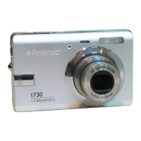
Polaroid t730
62 pages
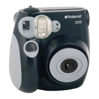
Polaroid PIC 300
2 pages
Polaroid DIGITAL 320
19 pages
Polaroid 600 Close-up
4 pages
Polaroid One600 Ultra
6 pages
Polaroid OneStep SX-70
21 pages
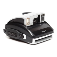
Polaroid impulse series
11 pages
Polaroid Digital Camera
67 pages