J,
R~'IlUWL'
thl..'
shUlh.'f
rc-k;IS!.'
hushing: from
the
l.';,IIlWTiJ.
tRr.:fr.:r
,n
pnX:l.'tlun.'
-Shulll'r
Rd,,'as..' Clbl<:
Repklt.:l,OlJll,Oot
and
Aujus{mcnt
of
Rd":::J~
Sulton."}
4.
SHd\!"
th~
focus
bar
to
extreme
CLOSE~UP.
un rhe
U-frmn~
up
until
it
is
frced from
the
pivot pin.
Saw
the
top
and
bottom
spacers
for
rellse.
Replacement
I. Insert the bottom spilcer
on
the
pivot pin.
Position the new
U-f,...lme
on
the
pivot
pin
and then slide
the
U~frarne
under
the
right
hand
glIilrd
.
.,
Install tht'
shutter
release bushing
and
cable
in
the
camera,
3. Hook
the
spring
onto
the
U~frame
bushing
and
slide
the
bushing
in
the
shutter
mouot
keyhole.
4.
Replace the top
and
bottom
inner
frame
link pivots
and
new
spacers. using tool
#111JO.
Work
the
focus bar back and
forth
a few times
to
be
sure
that
the
link. pivots
do
not
bind.
5.
Perform
the
applicable
RFjVF
and
lens
checks
described in Section Ill.
SHUTTER RELEASE
CABLE
REPLACEMENT
AND ADJUSTMENT
OF
RELEASE BUTTON
Removal
I.
Op.:n {he
bellows
to
detenl
lock"'n.
Loosr.:n
the
cable
release .:over
and
free
lhe
..
hlli!t"r !"'abk from the release cover.
3. Dt:pr.:"
...
Ill,;
~mllbl.'r
2
hunon
on
the
CJmcl"J
;lnd
('Ul
till"
lip
from tile'
end
of
the
shulIer
r
..
'kT'>~·
!::Jbk. Dis-.'ard tht'
Number::
button
_uld
win:.
but
:;:J\'" ttl\! spring,
In~~'rl
;1
1
16th"
il'H.'h
ddvt" pin
puncb
into
the
hll"hlD!!
;,JllI,}
geniI}' l:Jp
the
punch
!
I-I)!llrl'
5-~3}_
Thi:;
should
open
the
crimp
1
'IS"
T
A,P
GENT!.
'(
ORlvE
1"11\;
l'I,JIIICH
in
the
hushing
and
allow thl.'
l:.lhk
housing
to
fall
QUI.
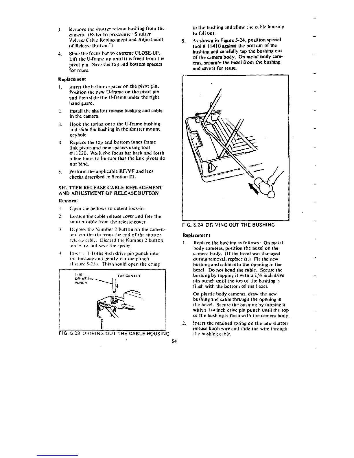
S.
As
shown
in
Figutt
5~24.
position
special
tool
II
11410
against
the
bottom
of
Ule
bushing
and
carefully
tap
the
bushing
out
of
the camera body. On metod body cam-
eras, separate
the
bezd
from
the
busbing
and
save it for reuse.
FIG. 0.24
DRIVING
OUT THE BUSHING
Replacement
1.
Replace
the
bushing as foHows:
On
metal
body
cameras,
position
the bezel
on
the
camera
body>
(If
the
bezel was damaged
during
removal. replace it.)
Fit
the
new
bushmg
and
cable
into
the
opening
in
the
bezel.
00
not
bend
the
cable.
Secure
the
bushing
by
lapping
it
with
J.
1/4
inch
drive
pin
punch
unt))
the
top
of
the
bushing
is
fillsh
with
the
bottom
of
the
bezel.
On
plastic
body
cameras.
draw
the
new
bushing
and
cable
through
the
opening
in
the
bezel. Secure the
bushing
by tapping
it
with
a
1/4
inch drive
pin
punch
unlil
the
top
of
the
bushing is flush
wilh
the
camera
body.
Insert
the
retained spring
on
the
new
shutter
release knob wire and slide the wire through
FIG. 5.23 DRIVING OUT THE CABLE HOUSING
the
bushing
cable,
54
 Loading...