-
-
-
-
-
-
-
-
-
-
-
-
-
-
-
pin
and
save
it
for future
use.
Make
no
al~
tempt
to replace
an
old
style
housing
with
another old style. Replace
it
with one
of
the
,newer models..
Attempt
to
salvage
the
metal
band
by
straight.rung the two
bottom
tabs
which
hold
it
to
the
housing.
Repla<:ement
I. Install the hardware
on
the
new
housing.
(Use the
hardware
salvaged from
the
old
housing. If a rivet
was
removed.
use
a
new
rivet
IA223947.)
Install
the
cantilever assembly
on
the
housing.
(If
the cantilever assembly is
of
an old style
and is being lnstalJed on a housing
with
a
locating pin.
you
will
note
that
there
is
no
hole on the assembly which corresponds with
the
location
of
the
pin.
It
is
then
necessary
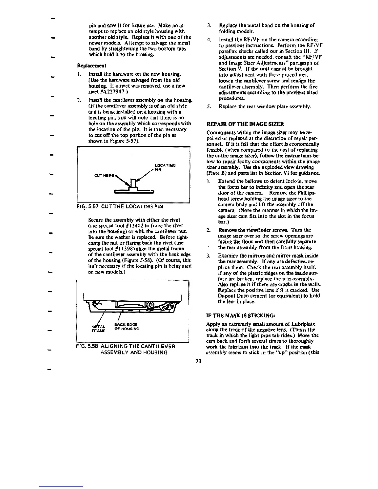
to cut
off
the
top portion
of
the pin
as
shown
in
Fignre 5-57).
LOCATING
PIN
CUTHER£
FIG. 5.57 CUT THE LOCATING PIN
Secure
the
assembiy with
either
the
rivet
(use special tooJ
111402
to
force
the
rivet
into the housing)
or
with the cantilever nut.
Se
sure
the
washer is replaced.
Before
tight~
ening the nut
or
flaring back the rivet (use
special tool *I
J3
98)
align
the
metal
frame
of
the
cantilever assembly with
the
back edge
of
the housing (Figure 5·58).
(Of
course. this
isn't necessary
If
the
locating
pin
is being used
on
new
models.)
FIG. 5.58
ALIGNING
THE CANTILEVER
ASSEMB
L Y AND HOUSING
73
3. Replace the metal band on the housing
of
folding models.
4.
Install the RF
/VF
on
the camera according
to previous instructions. Perform the
RF
/VF
parnIJax
checks
calJed
out
in
Section
m.
if
adjustments are needed. consult
the
"Rf
/VF
and
Image Sizer Adjustments" paragraph
of
Section
V.
If
the
unit
cannot be brought
into
adjustment with these procedures,
loosen the cantilever
screw
and realign the
cantilever assembly. Then perform
the
live
adjustments
according
to
the
previous
cited
procedures.
5,
Replace the rear window plate assembly.
REPAIR
Of
lHE
IMAGE
SlZER
Components within the image sizer
may
be re-
paired
or
replaced at the discretion
of
repair per·
sonnel.
If
it
is felt that the effort is economically
feasible
(when
compared
to
the
cost
of
replacing
the
entire
image sizer), foHow
the
instructions
be-
low
to
repair
faulty
components
within
the
image
sizer
assembly.
Use
the
exploded
view drawing
(Plate
8)
and
parts
Ust
in
Section
VI
for
gnidance.
1.
Extend the
bellOW's
to
detent
J<)ck:~in.
mOVe
the focus
bat
to
infmity
and
open the rear
door
of
the
camera. Remove
the
Phillips-
head screw
holding
the image sizer
to
the
camera body
and
lift
the
assembly
off
the
CJmen.
(Note the manner in wb.idt the im-
age sUer
cam
fits
into
the slot in
the
focus
bar.)
2. Remove
the
viewrmder
screws.
Tum
the
image sizer
over
so
the
screw openings
are
facing
the
floor
and
then carefuUy separate
the rear
~bly
from
the
front housing.
3. Examine the mirrors and mirror
mask:
inside
the
rear
assembly.
If
any
are
defective. re-
place them.
Cleek
the
rear assembly itself.
If
any
of
the piastic ridges
on
the
iIWde sur-
face are
bTOken~
replace the rear assembly.
Also
replace
it
jf
there are cracks in the waiJs.
Replace
the
positive lens if
it
is cracked. Use
Dupont
Duro
cement (or equivaient)
to.
hold
the lens
in
place.
If
lHE
MASK
IS
STICKING:
Apply
an
extremely smalJ
amount
of
LUbriplate
along
the
track
of
the
negative len$.
(This
is
the
track
in which
the
light
pipe
tab
rides.) Move
the
cam
back:
and forth several
times
to
thoroUghly
work
the tubric.ant into the trade.,
If
the
mask
assembly seems
to
stick in the
"up"
position
(this
 Loading...