imli..;,l!I,.'S
Ihilt lilt'
ll'l}>hguo
ml{!ht
h.,-
;In
,,";.Irly
mOth.,>j
with a 4.5 vde
battery
and
stainh:&:
sled
or
I'IIO'"p11or
bronze
dips.
ThL'$C
t1llshgOlls
must
be
np~'Il~tllor
in}>pcct'on. Jr
they
an: carly
model
na$h~\lIl:>.
t:onven them at."t'ording
to
pr<X:edures
in
~'etion
V
and
then
fest
them
as
indkatcd
below.
If
tilt'
border
around
the
instHidiolls
i,.
brok,-'o,
l,.'l)ntilll1l'"
with
the
Oashgull test
bl,.>low,
I.,
t'l:lCL'
a
:o;:pcdal
no--load
dummy
plug m
the
nash!!un and plug
the
flashgun info
th~
Uni~
v
..
'fsai Fklshgun Tester (see Figure 3-13), TIle
h:sh'r
should
be
S\:![
to
the
15
vdc:
scale.
.,
With the loggle
switch
in
the
proper
position
tri].e
~witch
revers\:!s
polarity).
the
indicator in
the
meter should move up
to
the
range
shown
in Figure
3-l4
(1.1 vdc
to
1.5 vdc).
If
the
ft~ading
is
less than this, replace rhe
battery.
If
there
is
no
reading
at
all, there is
an
open
in
the circuit. Open
the
flashgun
and
look for corroded
contacts
or
battery
wires.
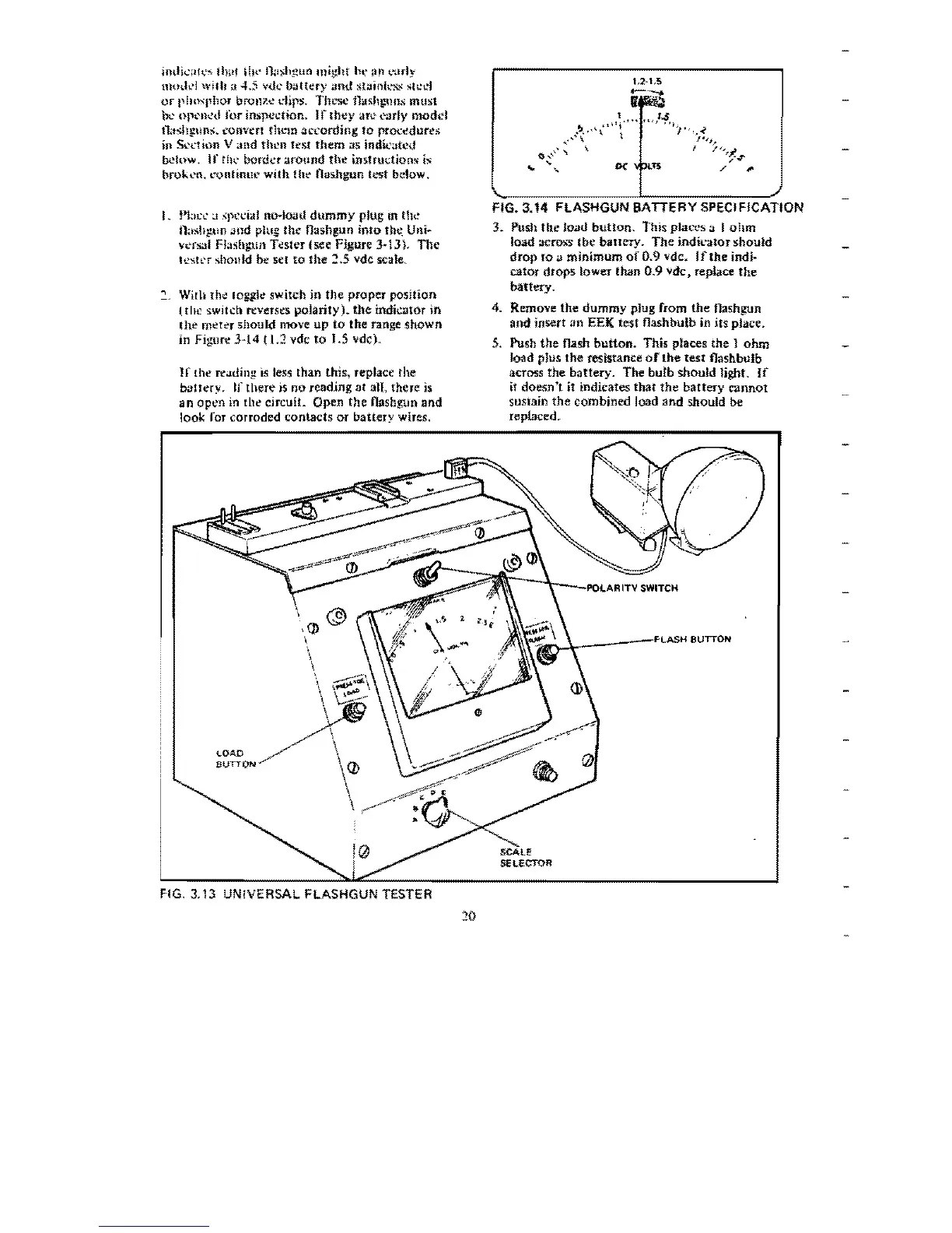
FIG. 3.14 FLASHGUN BATTERY SPECIFICATION
3. Push
the
load
button,
This places a I
ohm
load acro;.;s
tbe
battery.
The
indkatorshould
drop
ro
a
minimum
of
0.9 vdc.
If
the
indi·
cator
drops
lower than
0.9
vdc.
replace
the
battery
.
4.
Remove
the
dummy
plug
from
the
flashgun
and
insert
an
EEK test flashbulb in
its
pJace.
S.
Push
the
flash
button.
This places the 1
ohm
load
plus
the
resistance
of
the
teSl flashbulb
across
the
battery.
The bulb
should
light.
If
it
doesn'l
it indicates
that
the
battery
cannot
sustain
the
combined load
and
should be
replaced.
LOA.D
SUTTON
\--\--'POlARITV
SWITCH
~~
______
----F'LASH8UTTON
FIG, 3,13 UNIVERSAL FLASHGUN TESTER
20
 Loading...