PRE-INSTALLATION
© Polycom, Inc. 9 VORTEX EF2280 REFERENCE MANUAL
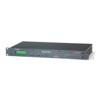
9. INPUT PARALLEL PORT. Parallel logic input.
10. O
UTPUT PARALLEL PORT. Parallel logic output.
11. EF B
US IN. Connects to EF BUS OUT of another EF2280.
12. EF B
US OUT. Connects to the EF BUS IN of another EF2280.
13. RS-232 S
ERIAL PORT. Connect this to an optional RS-232 remote control
device, such as a touch panel or personal computer COM port.
14. P
OWER SUPPLY INPUT. Connects to the external power supply provided with
the EF2280.
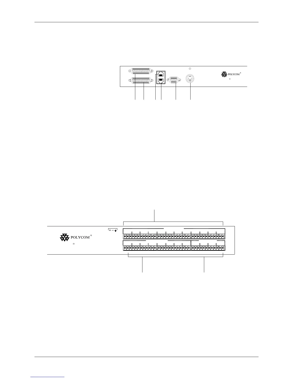
15. M
IC/LINE INPUTS. Connects to microphone at either mic or line level, with
or without phantom power.
16. L
INE INPUTS. Inputs A-D at line level.
17. L
INE OUTPUTS. Outputs 1-8 at line level, A-D at line level.
Figure 3. Parallel remote control, EF B
US, serial remote control, ASPI BUS
OUT, and power supply input on back panel of the EF2280.
RS-232 PIN 2: TXD, P IN 3: RX D, PIN 5: GROU ND, PIN 7: CTS, PIN 8: RTS
OUTPUT
INPUT
REMOTE CONTROL
EF BUS OUT
EF BUS IN
+5, +/-15 VDC
RS-232
ORTEXV EF2280
910 1112 13 14
Figure 4. Inputs and outputs on back panel of the EF2280.
61
MIC/LINE INPUTS
2 3 4 5
LINE INPUTS
7 8 A B C D
21 3 4 5
LINE OUTPUTS
6 7 B8 A C D
ORTEXV EF2280
15 16
17