PRE-INSTALLATION
VORTEX EF2280 Reference Manual 8 Technical Support: 800.765.9266
EF2280 F
RONT
AND
R
EAR
P
ANELS
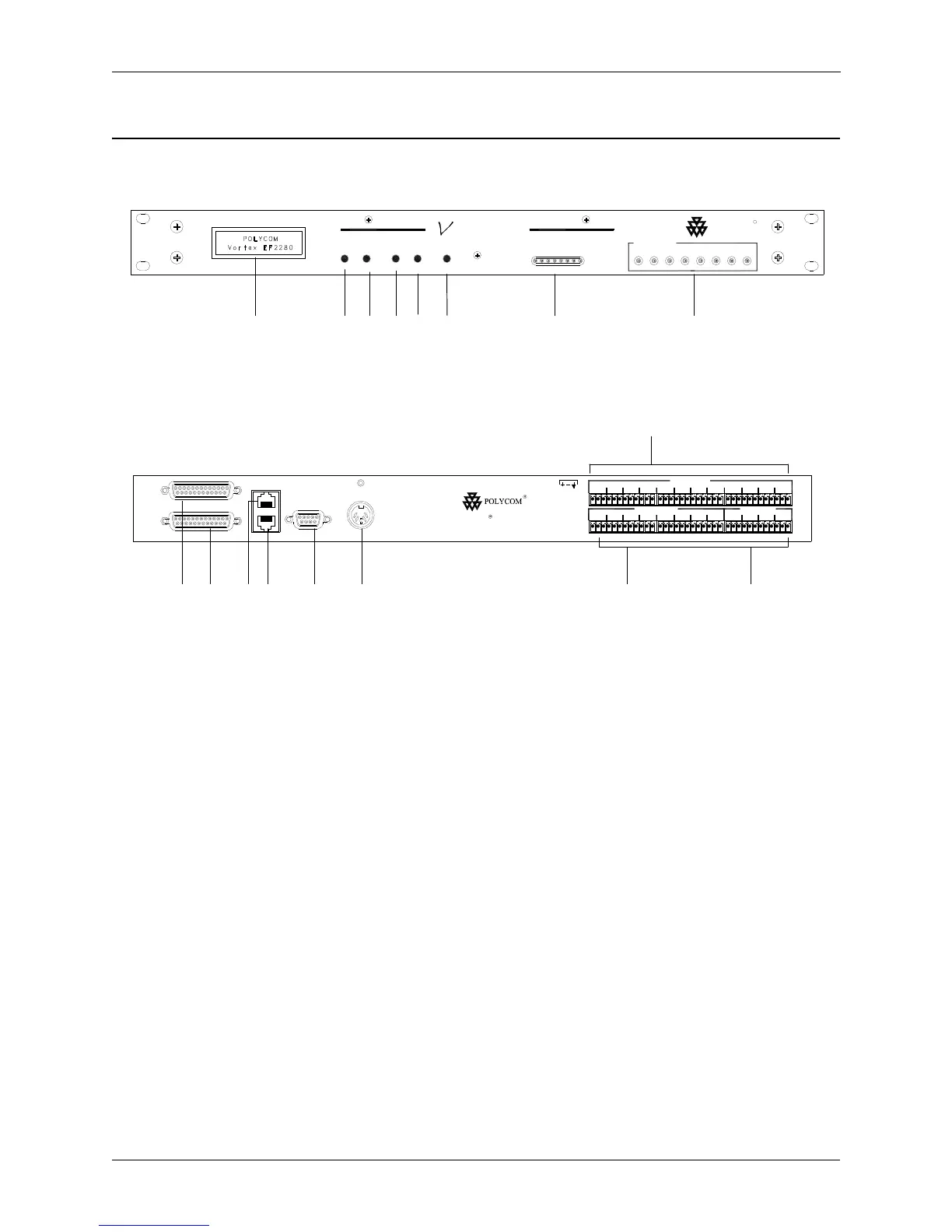
1. LCD DISPLAY. Displays menu instructions for configuration and operation
of the EF2280.
2. D
OWN BUTTON. Scrolls backward through menu items at a particular level
or decreases the value of a parameter.
3. U
P BUTTON. Scrolls forward through menu items at a particular level or
increases the value of a parameter.
4. E
NTER. Enters the menu and allows you to select and change parameter
values.
5. E
SC. Returns to the next highest level of menus.
6. H
OME. Returns to the top of the menu structure.
7. L
EVEL INDICATOR. Indicates the level of the selected channel or parameter.
8. C
HANNEL ACTIVITY LEDS. Indicates gating activity of the 8 mic/line channel
inputs.
Figure 2. EF2280 Front and Rear Panels
6
RS-232 PIN 2: TXD , PIN 3: RXD, PIN 5: GROUND, PIN 7: CTS, PIN 8: RTS
OUTPUT
INPUT
REMOTE CONTROL
EF BUS OUT
EF BUS IN
+5, +/-15 VDC
RS-232
1
MIC/LINE INPUTS
2 3 4 5
LINE INPUTS
7 8 A B C D
21 3 4 5
LINE OUTPUTS
6 7 B8 A C D
ORTEXV EF2280
910 1112 13 14 15 16
17
ORTEX
DOWN UP
ENTER
HOMEESC
-20 -12 -7 3
METER
-3 0 9 20 dB
CHANNEL ACTIVITY
122334456 87
EF2280
POLYCOM
R
1
2
354
8
7
6