INSTALLATION
VORTEX EF2280 Reference Manual 12 Technical Support: 800.765.9266
Typical EF2280
Connections
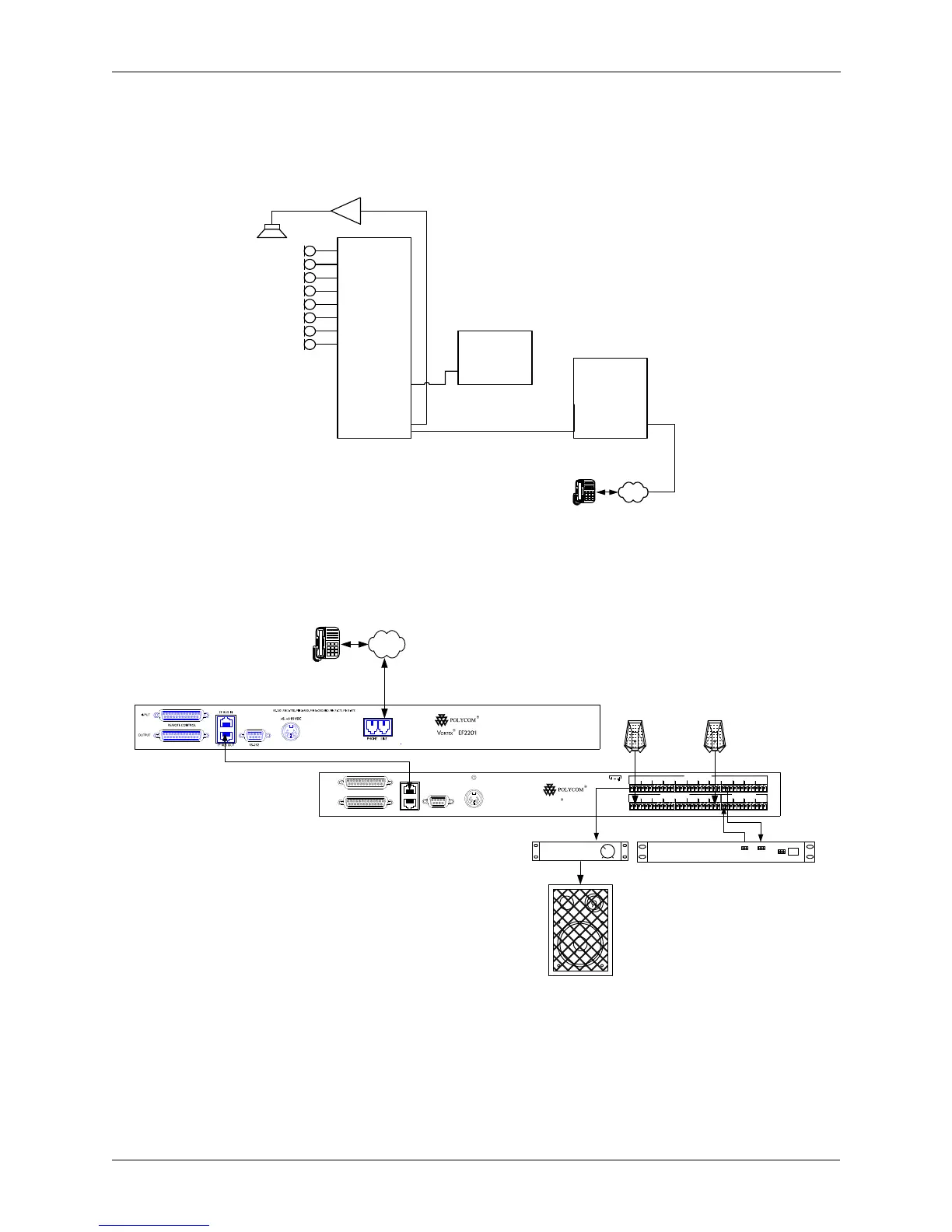
The EF2280 will typically be connected to other equipment in a single room
setup as shown below in Figure 5 and Figure 6.
Figure 5. Block diagram of typical EF2280 connections: a single room using one EF2280.
Figure 6. Typical EF2280 connections.
Vortex
®
EF2280
In 1
In 2
In 3
In 4
In 5
In 6
In 7
In 8
Out 1
Out 2
Out 3
Out 4
Out 5
Out 6
Out 7
Out 8
In A
In B
Out A
Out B
In D
Out C
Out D
In C
EF2201
Video
CODEC
Line In Line Out
PSTN
EF Bus
6
RS-232 PIN 2: TXD, PIN 3: RXD, PIN 5: GROUND, PIN 7: CTS, PIN 8: RTS
OUTPUT
INPUT
REMOTE CONTROL
EF BUS OUT
EF BUS IN
+5, +/-15 VDC
RS-232
1
MIC/LINE INPUTS
2 3 4 5
LINE INPUTS
7 8 A B C D
21 3 4 5
LINE OUTPUTS
6 7 B8 A C D
ORTEX
V
EF2280
. . .
8 microphones
PSTN
Vortex® EF2201 (Optional)
Polycom Video Codec
4-wire Connection
Room Amplifier
Vortex
®
EF2280
Audio
Amplifier
POLYCOM CODEC
TX RX